Sign In
Upload
Manuals
Brands
degdrive Manuals
DC Drives
DGI900
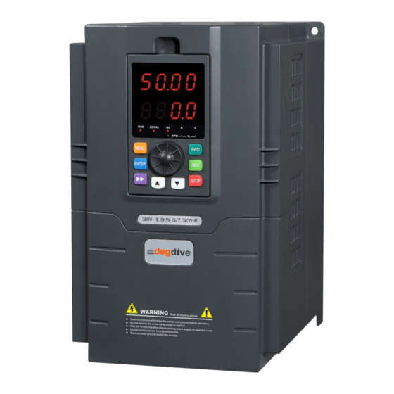
degdrive DGI900 Manuals
Manuals and User Guides for degdrive DGI900. We have
2
degdrive DGI900 manuals available for free PDF download: User Manual
degdrive DGI900 User Manual (252 pages)
Brand:
degdrive
| Category:
DC Drives
| Size: 2 MB
Table of Contents
Table of Contents
2
Chapter 1 Safety Precautions
5
Unpackage Inspection
5
Safety Information
6
Constant Torque Low Frequency Running
11
Motor Insulation Test
11
Hoist Load
11
Vibration of Mechanical Device
11
General Precautions
11
Voltage-Sensitive Device or Capacitor on Output Side of the AC Drive
12
Derate at Basic Frequency Setting
12
Running at over 50 Hz
12
Thermal Protection of Motor
12
Altitude and De-Rating
13
Protection Class
13
Disposal
14
Models Description
15
Chapter 2 Models and Specifications
15
Specifications
16
Parts of Inverter
21
Dimensions
21
Product View
21
Wall Mounting
22
Floor Mouthing
22
Optional Parts
23
Remote Control Keypad
23
Communication Cable for Remote Control Panel
24
Field Bus Adaptor
24
Braking Resistors
25
Environment Requirements
28
Mounting Space and Direction
28
Chapter 3 Installation and Wire Connection
28
Removing and Mounting Front Cover of Inverter
29
Mounting Space and Distance
29
Mounting of Multiple Inverters
29
Wire Connection
29
Main Circuit Wiring
30
Description of Main Circuit Input/Output Terminals
31
Basic Wiring Diagram
32
Control Circuit Terminal Wiring
32
Position and Function of Terminals and Jumpers on Control Circuit
32
Jumper Switch Function
33
Description of Terminals on Control Circuit
34
CN2 Terminal Function
35
Analog Input/Output Terminal Wiring
38
Communication Terminal Wiring
40
PLC Communication with Multi Inverters
41
EMC Installation Instruction
42
Noise Suppression
42
Wiring Connection and Grounding
44
Running of Inverter
46
Running Command Channels
46
Frequency Setting Channel
46
Chapter 4 Running of Inverter
46
Inverter Running States
47
JOG Running
47
Close Loop Running
48
PLC Running
48
Multi-Stage Speed Running
48
Normal Running
48
Operation and Using of the Control Panel
49
Control Panel Layout
49
Control Panel Function
50
LED Display and Indictor Description
51
Indicator State and Unit Indicating
51
Control Panel Display State
52
State Indicator Description
52
Parameter Displaying in Stopping State
52
Parameter Displaying in Running State
53
Fault Displaying in Alarm State
53
Function Code Programming State
54
Fault Alarm Display State
54
Control Panel Operation
54
Control Panel Programming State
54
Function Code Parameter Setting
55
Operation to Display Monitoring Parameter
55
JOG Running Operation
56
Password Authentication Operation
56
Inquiring Fault Related Parameter
57
Frequency Setting Operation by Control Panel Keys
57
Inverter Power Switch on
58
Control Panel Key Lock Operation
58
Control Panel Key Unlock Operation
58
Initial Power on Operation
58
Standard Function Parameters
60
Chapter 5 Function Code Table
60
Group P1: Start/Stop Parameter
65
Group P2: Auxiliary Functions
66
Group P3: Input Terminals
72
Group P4: Output Terminals
79
Group P5: V/F Control Parameters
82
Group P6: PID Function
84
Group P7: Operation Panel and Display
88
Group P8: Motor Parameters
92
Group P9: Vector Control Parameters
94
Group PA: Fault and Protection
98
Group PB: Multi-Reference and Simple PLC Function
106
Group PC: Communication Parameters
112
Group Pd: Function Code Management
113
Group PE: Swing Frequency, Fixed Length and Count
114
Group PF: AIAO Correction and AI Curve Setting
115
Group E0: User-Defined Parameters
118
Group B: Standard Monitoring Parameters
119
Basic Parameters(Group P0)
122
Main Frequency Source 1 Selection
122
Chapter 6 Description of Function Codes
122
Preset Frequency
123
Command Source Selection
124
Rotation Direction
124
Maximum Frequency
124
Frequency Upper Limit
124
Frequency Lower Limit
125
Source of Frequency Upper Limit
125
Frequency Upper Limit Offset
125
Carrier Frequency
125
Carrier Frequency Adjustment with Temperature
126
Acceleration Time
126
Deceleration Time
126
Time Base Frequency
128
Frequency Source Selection
128
Range of Auxiliary Frequency
128
Minimum
129
Frequency Offset of Auxiliary Frequency Source for 1 and 2 Operation
129
Frequency Reference Resolution
129
Retentive of Digital Setting Frequency Upon Power Failure
129
Base Frequency for UP/DOWN Modification During Running
130
Binding Command Source to Frequency Source
130
G/P Type Display
131
Motor Parameter Group Selection
131
Start/Stop Control(Group P1)
132
Serial Communication Protocol
132
Rotational Speed Tracking Restart
132
Pre-Excited Start
132
Startup Frequency
133
Startup DC Braking Current/Pre-Excited Current
133
Startup DC Braking Time/Pre-Excited Time
133
Stop Mode
134
Decelerate to Stop
134
Coast to Stop
134
Waiting Time of Stop DC
134
Stop DC Braking Time
135
Brake Use Ratio
135
Rotational Speed Tracking Mode
136
Stop DC Braking Process
136
Rotational Speed Tracking Speed
136
Acceleration/Deceleration Mode
136
Time Proportion of S-Curve Start Segment
137
Time Proportion of S-Curve End Segment
137
Auxiliary Functions(Group P2)
138
JOG Operation
138
Forward/Reverse Rotation Dead-Zone Time
140
Principle of the Jump Frequencies and Jump Amplitude
140
Reverse Control
140
Running Mode When Set Frequency Lower than Frequency Lower Limit
140
Drop Control
141
Accumulative Power-On Time Threshold
141
Accumulative Running Time Threshold
141
Startup Protection
141
Frequency Detection Value (FDT1)
142
Frequency Detection Hysteresis (FDT1)
142
Detection Range of Frequency Reached
143
Jump Frequency During Acceleration /Deceleration
144
Diagram of any Frequency Reaching Detection
145
Acceleration/Deceleration Time Switchover
146
Terminal JOG Preferred
146
Zero Current Detection
147
Output Overcurrent Threshold
148
Output Overcurrent Detection Delay Time
148
Any Current Reaching
149
Timing Function
150
Timing Duration Selection
150
Timing Duration
150
VI Input Voltage Lower Limit
151
VI Input Voltage Upper Limit
151
Module Temperature Threshold
151
Cooling Fan Control
151
Wakeup Frequency
152
Wakeup Delay Time
152
Dormant Frequency
152
Dormant Delay Time
152
Input Terminals(Group P3)
153
Current Running Time Reached
153
Functions of XI Terminals
153
Forward/Reverse JOG
155
Terminal UP/ Terminal down
155
Multi-Reference Terminal
156
Fault Reset (RESET)
156
RUN Pause
156
Normally Open (NO) Input of External Fault
156
Multi-Reference Wiring Diagrams
157
Acceleration/Deceleration Time Selection
158
Frequency Source Switchover
158
UP and down Setting Clear (Terminal, Operation Panel)
158
Command Source Switchover Terminal
158
Acceleration/Deceleration Prohibited
159
PID Pause
159
PLC Status Reset
159
Length Count Input
159
Frequency Modification Forbidden
160
Reverse PID Action Direction
160
External STOP Terminal 1
160
Command Source Switchover Terminal 2
160
Emergency Stop
161
External STOP Terminal 2
161
Deceleration DC Braking
161
Switchover between Auxiliary Frequency Source y and Preset Frequency
161
VI Function Selection (DI)
162
CI Function Selection (DI)
162
Relationship of AI Input Voltage and Corresponding DI Status
163
X Filter Time
163
Terminal Command Mode
163
Two-Line Mode 1/2
164
Three-Line Mode 1
164
Terminal UP/DOWN Rate
165
VI Curve 1 Minimum Input
165
Corresponding Setting of VI Curve 1 Minimum Input
165
VI Curve 1 Maximum Input
165
Corresponding Relationship between Analog Input and Set Values
168
VI Curve Selection
168
Setting for VI Less than Minimum Input
169
X1-3 Delay Time
169
X Valid Mode Selection
169
Output Terminals(Group P4)
170
FM Terminal Output Mode
170
Functions of Output Terminals
171
FMP Function Selection
176
AO1 Function Selection
176
AO2 Function Selection
176
The Relationship between Pulse and Analog Output Ranges
177
Maximum FMP Output Frequency
178
AO1/2 Offset Coefficient
178
AO1/2 Gain
178
FM Output Delay Time
178
V/F Control Parameter(Group P5)
179
V/F Curve Setting
179
Relay1/2 Output Delay Time
179
DO Valid Mode Selection
179
Torque Boost
180
Manual Torque Boost
182
Setting of Multi-Point V/F Curve
182
V/F Slip Compensation Gain
182
Cut-Off Frequency of Torque Boost
182
V/F Over-Excitation Gain
183
V/F Oscillation Suppression Gain
183
Voltage Source for V/F Separation
184
PID Function(Group P6)
185
Communication Setting
185
Principle Block Diagram of PID Control
186
PID Setting Source
186
PID Digital Setting
186
PID Feedback Source
186
PID Setting Feedback Range
187
Proportional Gain Kp1
187
Integral Time Ti1
187
Differential Time Td1
187
Cut-Off Frequency of PID Reverse Rotation
188
PID Deviation Limit
189
PID Differential Limit
189
PID Setting Change Time
189
PID Feedback Filter Time/Pid Output Filter Time
189
PID Parameters Switchover
191
PID Initial Value
191
PID Initial Value Holding Time
191
Maximum Deviation between Two PID Outputs in Forward Direction
191
Maximum Deviation between Two PID Outputs in Reverse Direction
192
PID Integral Property
192
Operation Panel and Display(Group P7)
193
REV Key Function Selection
193
Detection Value/Time of PID Feedback Loss
193
PID Operation at Stop
193
STOP Key Enabled in any Operation Mode
194
STOP Key Function
194
LED Display Running Parameter
194
LED Display Stop Parameter
195
Load Speed Display Coefficient
195
Heatsink Temperature of Inverter Module
196
Temporary Software Version
196
Accumulative Running Time
196
Number of Decimal Places for Load Speed Display
196
Motor Parameters(Group P8)
197
Accumulative Power-On Time
197
Accumulative Power Consumption
197
Encoder Pulses Per Revolution
199
Encoder Type
199
A/B Phase Sequence of ABZ Incremental Encoder
199
Number of Pole Pairs of Resolver
199
Auto-Tuning Selection
200
Torque Control and Vector Control Parameters (Group P9)
201
Speed/Torque Control Selection
201
ASR Speed Loop Proportional Gain Kp1
201
Switchover Frequency 1
201
ASR Speed Loop Integral Time Ti2
202
Relationship between Running Frequencies and PI Parameters
202
Vector Control Slip Gain
203
Time Constant of Speed Loop Filter
203
Vector Control Over-Excitation Gain
204
Torque Upper Limit Source in Speed Control Mode
204
Digital Setting of Torque Upper Limit in Speed Control Mode
204
Excitation Adjustment Proportional Gain
205
Torque Adjustment Proportional Gain
205
Torque Setting Source in Torque Control
205
Torque Digital Setting in Torque Control
205
Parameter Protection(Group PA)
206
Forward Maximum Frequency in Torque Control
206
Acceleration Time in Torque Control
206
Deceleration Time in Torque Control
206
Motor Overload Protection Selection
207
Motor Overload Protection Gain
207
Motor Overload Warning Coefficient Setting Range
207
Over Voltage Stall Gain
208
Over Voltage Stall Protective Voltage
208
Overcurrent Stall Gain
209
Overcurrent Stall Protective Current
209
Fault Auto Reset Times/Do Action During Fault Auto Reset
210
Time Interval of Fault Auto Reset
210
Input Phase Loss Protection/Contactor Energizing Protection Selection
210
Output Phase Loss Protection Selection
210
Fault Protection
212
Frequency Selection for Continuing to Run Upon Fault
213
Backup Frequency Upon Abnormality
214
Motor Overheat Protection Threshold
214
Motor Overheat Warning Threshold
214
Voltage Rally Judging Time at Instantaneous Power Failure
214
Protection Upon Load Becoming 0
216
Detection Level of Load Becoming 0
216
Detection Time of Load Becoming 0
216
Over-Speed Detection Value/Over-Speed Detection Time
216
Multi-Reference and Simple PLC Function(Group Pb)
217
Detection Value of too Large Speed Deviation
217
Detection Time of too Large Speed Deviation
217
Multi-Reference 0 to Multi-Reference 15
217
Simple PLC Running Mode
218
Simple PLC Retentive Selection
219
Running Time of Simple PLC Reference 0
219
Function Code Parameter(Group Pd)
220
Communication Parameter ( Group PC
220
Restore Default Settings
221
AC Drive Parameter Display Property
221
Parameter Modification Property
221
Swing Frequency, Fixed Length and Count(Group PE)
222
Swing Frequency Control
222
Swing Frequency Setting Mode
223
Swing Frequency Amplitude
223
Jump Frequency Amplitude
223
Triangular Wave Rising Time Coefficient
224
Set Length
224
Actual Length
224
Number of Pulses Per Meter
224
AI/AO Correction and AI Curve Setting(Group PF)
225
Set Count Value
225
Designated Count Value
225
VI Measured Voltage
225
VI Displayed Voltage
226
CI Measured Voltage
227
CI Displayed Voltage
227
AO1 Target Voltage
227
AO1 Measured Voltage
227
Jump Point of VI Input Corresponding Setting
228
Jump Amplitude of VI Input Corresponding Setting
228
AO2 Measured Voltage
228
AO2 Target Voltage
228
User-Defined Function Codes(Group E0)
229
Motor 2 to Motor 4 Parameters(Group E3、E4、E5)
229
Standard Monitoring Parameters(Group B0
230
Fault Alarm and Troubleshooting
231
Chapter 7 Troubleshooting
231
Fault Record Search
236
Fault Reset
236
Chapter 8 Preservation and Maintenance
237
Periodic Inspections
238
Thermally Maintaining
238
Frequency Inverter Parts Replacement
238
Periodic Preservation and Maintenance
238
Warranty of Inverter
239
Chapter 9 Serial Port RS485 Communication Protocol
239
Communication Overview
239
Communication Protocol Specification
240
Communications Networking Methods
240
RTU Protocol
241
Communication Interface
241
Control Command Address
245
CRC Check
247
Read Command Frame
248
Read Command Response Frame
248
Parameter Description
249
Write Command Frame
249
Write Command Response Frame
249
Data Format
250
Local Address
250
Response Delay
250
Communication Timeout
251
Read Data Return Format Selection
251
Advertisement
degdrive DGI900 User Manual (217 pages)
Brand:
degdrive
| Category:
DC Drives
| Size: 5 MB
Table of Contents
Preface
2
Table of Contents
3
Chapter 1 Precautions
6
Safety Precautions
6
Precautions for Use
9
Disposal Considerations
11
Chapter 2 Product Introduction
12
Naming Rules
12
Nameplate Information
12
Series and Models
13
Specifications
14
Products Apperance
17
Installation Size
18
Optional Parts
22
Chapter 3 Installation and Wire Connection
24
Mechanical Installation
24
Standard Wiring
25
EMC Installation Instruction
36
Chapter 4 Operation and Operation Examples
40
Initial Power-Up
40
Inverter Operation
41
Keypad Introduce
43
Display Status
46
Property Description
52
Function Code Table
57
Chapter 6 Detailed Function Parameter Description
92
Group P0 Standard Function Parameter
92
Group P1 Start/Stop Parameter
102
Group P2 Auxiliary Functions
107
Group P3 Input Terminals
120
Group P4 Output Terminals
134
Group P5 V/F Curve Parameters
142
Group P6 PID Function Parameters
147
Group P7 Operation Panel and Display
154
Group P8 Motor Parameters
157
Group P9 Vector Control Parameters
160
Group PA Fault and Protection
166
Group Pb Multi-Reference and Simple PLC Function
176
Group PC Communication Parameter
179
Group Pd Function Code Management
179
Group PE Swing Frequency, Fixed Length and Count
180
Group PF AI/AO Correction and AI Curve Setting
184
Group E0 Ser Function Code Parameter
186
Group E9 Protection Function Parameter
187
2Nd, 3Rd, and 4Th Motor Parameters (E3, E4, E5 Groups)
190
Monitoring Parameter Group-Operation Parameter Monitoring (Group B0)
190
Chapter 7 Fault Diagnosis and Processing
191
Failure Phenomena and Countermeasures
191
Fault Record Query
195
Fault Reset
195
Chapter 8 Maintenance and Maintenance E
197
Daily Maintenance and Maintenance
197
Warranty Description
198
Chapter 9 Serial Port RS485 Communication Protocol
200
Communication Overview
200
Communication Protocol Description
200
Communication Protocol
202
Chapter 10 Appendix
210
Advertisement
Related Products
degdrive DGI900-4T0007G
degdrive DGI900-4T0015P
degdrive DGI900-4T0015G
degdrive DGI900-4T0022P
degdrive DGI900-4T0022G
degdrive DGI900-4T0037G
degdrive DGI900-4T0037P
degdrive DGI900-4T0055G
degdrive DGI900-4T0055P
degdrive DGI900-4T0075G
degdrive Categories
DC Drives
Inverter
More degdrive Manuals
Login
Sign In
OR
Sign in with Facebook
Sign in with Google
Upload manual
Upload from disk
Upload from URL