Table of Contents
Advertisement
Quick Links
Advertisement
Table of Contents

Related Manuals for degdrive DGI900 Series

Summary of Contents for degdrive DGI900 Series
- Page 1 User Manual DGI900...
-
Page 2: Preface
Preface DGI900 series is the new generation products to meet general purpose and special technical demand. The new designed sensorless vector control performance of DGI900 inverter have improved the reliability at low speed, the overload capacity at low frequency and high control precision at open loop tension control mode. -
Page 3: Table Of Contents
Contents Preface · · · · · · · · · · · · · · · · · · · · · · · · · · · · · · · · · · · · · · · · · · · · · · · · · · · · · · · · · · · · · · · · · · · · · · · · · · · · · · · · · · · · · · · · · · · · · · · · · · · · · · · · · · · · 1 Chapter 1 Precautions ·... - Page 4 5.1 Property description · · · · · · · · · · · · · · · · · · · · · · · · · · · · · · · · · · · · · · · · · · · · · · · · · · · · · · · · · · · · · · · · · · · · · · · · · · · · · · · · · · · · · 51 5.2 Function code table ·...
- Page 5 Chapter 8 Maintenance and Maintenance e · · · · · · · · · · · · · · · · · · · · · · · · · · · · · · · · · · · · · · · · · · · · · · · · · · · · · · · 195 8.1 Daily maintenance and Maintenance ·...
-
Page 6: Chapter 1 Precautions
Chapter 1 Precautions 1.1 Safety Precautions The use phase Safety class Precaution Do not install the product if the package is with water, or component is missing or broken; Do not install the product if the label on the Danger package is not identical to that on the inverter. - Page 7 The use phase Safety class Precaution Wiring must be performed by authorized and qualified personnel. Risk of danger. Circuit-breaker should be installed between inverter and the mains. Risk of fire. Make sure the input power supply has been completely disconnected before wiring.
- Page 8 The use phase Safety class Precaution recommended output AC reactor be used. Failure to comply may result in faults. Inverter shall be power-on only after the front cover is assembled. Risk of electrical hazard. Danger Verify that the input voltage is identical to the Before rated voltage of product, correct wiring of input Power-on...
-
Page 9: Precautions For Use
1.2.2 Confirmation of motor insulation When applying the DGI900 series inverter, please confirm the insulation of the motor before using the motor to prevent damage to the equipment. In addition, please check the insulation of the motor regularly when the environment of the motor is bad, to ensure the safe operation of the system. - Page 10 should be considered. 1.2.4 Mechanical resonance point of the load device The inverter may encounter the mechanical resonance point of the load device within a certain range of output frequency, and must be avoided by setting the jump frequency. 1.2.5 Capacitance or varistor for improving power factor Since the output voltage of the inverter is pulse wave type, if the output side is equipped with a capacitor with improved power factor or a varistor for lightning protection, it will cause the inverter to trip or damage the device.
-
Page 11: Disposal Considerations
1.2.9 Altitude and derating In areas where the altitude is more than 1000 meters, the heat dissipation effect of the inverter is deteriorated due to the thin air, and it is necessary to derate the use. Figure 1-2 shows the relationship between the rated current of the inverter and the altitude. Figure 1-2 Inverter rated output current and altitude derating diagram 1.2.10 About the degree of protection The protection level IP20 of the DGI900 inverter refers to the degree of protection achieved... -
Page 12: Chapter 2 Product Introduction
Chapter 2 Product Introduction 2.1 Naming rules DGI900- 4 T 0015 G Abbreviatio Code Inverter type Constant torque Voltage Code Pump& Fan 220V 380V Code Power rate Input voltage 0007 0.75KW Code 0015 1.5KW Single phase 0075 7.5KW Three phases Fig 2-1. -
Page 13: Series And Models
Fig 2-2. Name Designation Rules 2.3 Series and Models Rated Model Rated Applicable Voltage output capacity Motor level Current (KVA) G Type P Type (KW) (A) DGI900-4T0007G DGI900-4T0015P 0.75 DGI900-4T0015G DGI900-4T0022P DGI900-4T0022G DGI900-4T0022P DGI900-4T0037G DGI900-4T0037P DGI900-4T0055G DGI900-4T0055P 14.0 DGI900-4T0075G DGI900-4T0075P 17.0 DGI900-4T0110G DGI900-4T0110P... -
Page 14: Specifications
Rated Model Rated Applicable Voltage output capacity Motor level Current (KVA) G Type P Type (KW) (A) DGI900-4T3500G DGI900-4T3500P DGI900-4T4000G DGI900-4T4000P DGI900-4T4500G DGI900-4T4500P DGI900-4T5000G DGI900-4T5600P DGI900-4T5600G DGI900-4T6300P DGI900-4T6300G DGI900-4T7100P 1100 2.4 Specifications Items Specifications Rated Voltage Three phase 380V / 415V / 440V/460V; 50Hz/60Hz Input Voltage: ±20% voltage unbalance rate:<3%;... - Page 15 Items Specifications Five ways: constant torque V/F curve, 1 kind of user defined V/F curve V/F curve ,3 kinds of down torque curve (2.0/1.7/1.2times the power) Two ways: linear Acc./Dec., S-curve Acc./Dec.;7 kinds of Acc./Dec. Acc./Dec. time, Time unit(minute/second) optional, max. curve time: 6000 minutes.
- Page 16 Items Specifications Control panel potentiometer setting: ▲、▼control panel keys setting; Function code setting: Serial port setting; Frequency Terminal up/down setting: Input Analog voltage setting: setting Input Analog current setting: Input pulse setting; channel Combination ways setting; Running Above ways are switchable. function 8 digital input terminals, 1 of which supports up to 100KHZ high speed pulse input...
-
Page 17: Products Apperance
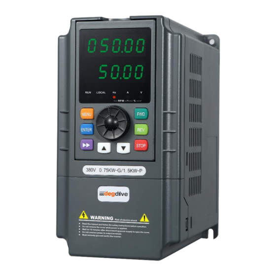
Items Specifications Storage -20℃~+60℃ temperature Protection IP20(In the selection of state display unit or the keyboard level state) Structure Cooling Forced air cooling Installation Wall mounted; Floor mounted 2.5 Products apperance Fig 2-3 parts of Inverter... -
Page 18: Installation Size
2.6.1 0.75~7.5KW (Wall mounting) Fig 2-4 Inverter Model Mount (mm) (mm) (mm) (mm) (mm) hole G Type P Type DGI900 series/Input voltage: 220V single phase DGI900-2S0004G Φ5 DGI900-2S0007G DGI900-2S0015G Φ5 DGI900-2S0022G DGI900 series/Input voltage: 380V three-phase DGI900-4T0007G DGI900-4T0015P Φ5 DGI900-4T0015G... - Page 19 2.6.2 11~90KW (Wall mounting) Fig 2-5 Inverter Model Mount (mm) (mm) (mm) (mm) (mm) hole G Type P Type DGI900 series/Input voltage: 380V three-phase DGI900-4T0110G DGI900-4T0150P Φ6 DGI900-4T0150G DGI900-4T0185P DGI900-4T0185G DGI900-4T0220P Φ6 DGI900-4T0220G DGI900-4T0300P DGI900-4T0300G DGI900-4T0370P Φ8 DGI900-4T0370G DGI900-4T0450P DGI900-4T0450G DGI900-4T0550P Φ10...
- Page 20 2.6.3 132~250KW (Wall mounting) Fig 2-6 Inverter Model Mount (mm) (mm) (mm) (mm) (mm) hole G Type P Type DGI900 series/Input voltage: 380V three-phase DGI900-4T1320G DGI900-4T1600P Φ14 DGI900-4T1600G DGI900-4T1850P DGI900-4T1850G DGI900-4T2000P Φ14 DGI900-4T2000G DGI900-4T2200P P P P P G DGI900-4T2200G...
- Page 21 2.6.4 280~315KW (Floor mouthing) Fig 2-7 Fig 2-8 Inverter Model W(mm) H(mm) D(mm) G Type P Type DGI900-4T2800G DGI900-4T3150P 1400 DGI900-4T3150G DGI900-4T3500P 2.6.5 350~630KW (Floor mouthing) Inverter Model W(mm) H(mm) D(mm) G Type P Type DGI900-4T3500G DGI900-4T4000P 1700 DGI900-4T4000G DGI900-4T4500P DGI900-4T4500G DGI900-4T5000P 1900...
-
Page 22: Optional Parts
2.7 Optional Parts: 2.7.1 Braking resistor In the DGI900 series inverter, the inverter below 22KW(including 22KW) contains the braking unit. If there is energy consumption braking requirement, please select the braking resistor according to the following table. The connection of the braking resistor is shown in Figure 2-8. - Page 23 Applicable Resistanc Resistance Model Braking unite e (Ω ) motor (KW) power (W) DGI900-4T0185G 18.5 4000 Built in DGI900-4T0220G 4000 Built in Built in or DGI900-4T0300G 6000 External Built in or DGI900-4T0370G 9000 External DGI900-4T0450G 13.6 9000 External DGI900-4T0550G 20*2 12000 External DGI900-4T0750G...
-
Page 24: Chapter 3 Installation And Wire Connection
Chapter 3 Installation and Wire Connection 3.1 Mechanical installation 3.1.1 Installation Environment Please mount inside a well-ventilated location. The ambient temperature is required to be within the range of -10 ~40℃. If the temperature is higher than 40 ℃, the inverter should be derated, at the same time the ventilation and heat dissipation should be enhanced. -
Page 25: Standard Wiring
Fig.3-1 Mounting space and distance Fig.3-2 Mounting of multiple inverters 3.2 Standard Wiring 3.2.1 Wiring precautions Security Level Safety Precautions Before wiring, please ensure the power has been removed and be wait for at least 10minutes. Please do not connect AC power to output terminals U/V/W. ... - Page 26 Security Level Safety Precautions wiring of relay input/output loop (X1~X6, FWD, REV, OC, DO).One end of shielding layer suspended, and the other side connected to PE grounding terminal of inverter, wiring length less than 50m . The cover can be removed only when the power is switched off, all the LEDs on the panel are off and waiting at least for 10 minutes.
- Page 27 3.2.2.2 Schematic diagram of the main circuit terminal Apply Terminal Main circuit terminal Function name 220V single phase Input 220V L1、L2 terminals single 380V 3 phase Output phase U、V、W terminals 0.4KW~ 2.2KW Earthing 380V 3 phase Input R、S、T terminals 380V 3 phase 380V 3 phase Output U、V、W...
- Page 28 3.2.3 Basic Wiring Diagram Fig. 3-4 Basic Wiring Diagram 3.2.4 Control loop configuration and wiring 3.2.4.1 Jumper switch and control board terminal position and function introduction The relative positions of the jumpers and terminals on the control board are shown in Figure 3-5.
- Page 29 function description of each terminal, see Table 3-3. Before the inverter is put into use, all the jumper switches on the terminal wiring and setting control board should be correctly performed. It is recommended to use more than 1mm wire as the terminal connection line. Fig.
- Page 30 Function Setting Setting Factory default I side connection: CI: 0~20MA or 4~20MA CI termial current/ voltage Factory input 0-10V input input selection default V side connection: CI: 0~10V input Pulse output te Table 3-2 Jumper switch function table 3.2.4.3 Control board terminal CN1 Sort Terminal Setting...
- Page 31 Sort Terminal Name Function Specification RS485 differential signal positive 485+ terminal Twisted or shielded RS485 interface RS485 differential signal negative wire needed 485- terminal Optical coupling isolation, dual polarity open collector output Couple output Note: CME and COM are Output voltage range: Open internally insulated, but they are 0–24 V...
- Page 32 Sort Terminal Name Function Specification Analog voltage/ current output, Current output range: voltage/ current selected by 4~20mA Analog Jumper AO2,voltage output as output AO2 Voltage output range: default. (Common terminal: 0~10V GND). Multifunction al input Can be defined as multifunctional terminal 1 on-off input terminal by Multifunction...
- Page 33 Sort Terminal Name Function Specification +10V Grounding of analog signal common Terminal COM and and+10V power source terminal GND are Digital signal input, output Isolated inside +24Vcommo n terminal common terminal Table 3-4 Control board CN2 terminal function table (continued above) 3.2.5 Analog Input/Output Terminal Wiring (1) Analog voltage signal input through VI terminal as follow wiring:...
- Page 34 (3) Analog output terminal AO1 wiring Analog output terminal can be connected with external analog meter indicating various physical quantity, jumper selection for output voltage (0~10V) or output current (4~20mA) as follow wiring: Fig. 3-9 Analog output terminal wiring (4) Digital output terminal DO wiring When DO connect to relay, the replay have to connect with diode.
- Page 35 (2) Please use shielded cable and do well grounding, keep the wire as short as possible in order to prevent external interference when using analog input/o output mode. 3.2.6 Communication Terminal Wiring The inverter supplies standard RS 485 communication port It can constitute one master one slave control system or a one master multi slaves system.
-
Page 36: Emc Installation Instruction
(3) Multi inverters can communicate via RS485, controlled by PC/PLC as a Master shown as Fig.3-12. It also can be controlled by one of inverters as a Master shown as Fig.3-13 Fig. 3-12 PLC communication with multi inverters Fig. 3-13 Multi inverters communication The more inverters connected, the more the communication interference may accure. - Page 37 3.3.1 Noise Suppression Noise is unavoidable during inverter operation. Its influence over peripheral equipment is related to the noise type, transmission means, as well as the design, install action, wiring and grounding of the driving system (2) Noise Suppression Methods Path Noise suppression methods If a closed loop is formed between the peripheral equipment and the inverter...
- Page 38 Path Noise suppression methods Equipment and signal lines that are susceptible to interference should be installed as far as possible from the inverter. The signal line should be shielded. The shield should be grounded at one end and should be as far away as possible from the inverter and its input and output lines.
- Page 39 20cm from each other. If cable crossing is inevitable, please make sure it is same as Fig.3-1 4 Please ground the control signal cable separately with power cable/motor cable. Please don’t connect other devices to inverter power input terminals(R/S/T). Fig.
-
Page 40: Chapter 4 Operation And Operation Examples
Chapter 4 Operation and operation examples 4.1 Initial power-up Please follow the wiring requirements in Chapter 3 "Installation and Wiring" in this manual. After the wiring and power check are confirmed, close the AC power switch on the input side of the inverter to power on the inverter. -
Page 41: Inverter Operation
4.2 Inverter operation 4.2.1 Inverter Operation Command Channel Command Control method Channel Keys o on the panel to control the inverter.(Factory Panel operatio default ) Control Use one of terminals amongX1~X7 and COM to constitute a 2-wire control terminal mode. ... - Page 42 4.2.3 Inverter Running States When inverter power on, there are two states which are Standby and running state. Working Description status When power switch on, inverter will be in standby state before receiving Standby control command. Or receiving Stop command during inverter running, state inverter will stop and standby.
-
Page 43: Keypad Introduce
Fig. 4-2 Logical relationship diagram of inverter running status The above 5 kinds of running modes can be running in multiple frequency setting channel except JOG running. PLC running, multi-stage speed running and normal running can carry out swing frequency running 4.3 Keypad introduce 4.3.1 Keypad interface The operation panel and control terminals of the inverter can control the starting, speed... - Page 44 Fig. 4-3 Control panel diagram 4.3.2 Keypad Function description Name Description When the light is on, the inverter is in the running state; when the light is off, the inverter is in the stop state. Indicates that the inverter is in ○...
- Page 45 Name Description Voltage unit Speed unit Percentage Name Description There are 5 5-segment LED digital tubes on the operation panel of the inverter, which display various monitoring data such as setting frequency, output frequency and alarm codes. Digital Corresponding Digital Corresponding Digital Corresponding...
-
Page 46: Display Status
Name Description When VFD at normal running , press this button to stop Inverter as pre-setting way. Stop/Reset When VFD has fault, press this button to reset the inverter back to normal status. Enter or exit programming status Menu/Data Data or function code increment Increment Data or function code decrement Decrement... - Page 47 Figure A Figure B Figure C Power on to initialize the Stop status, display Running status, showing the display dynamic picture downtime parameter operating status parameters Fig. 4-4 Parameter display in initialization, stopping and running state 4.4.2 Running Parameter Display Status After getting a valid running comman, Inverter enters runing status and the operating keyboard displays the running status monitoring parameters.
- Page 48 Fig. 4-5 Fault alarm display state Remark: For some serious faults, such as inverter module protection, over current, over voltage,etc. It is absolutely impossible to force the fault reset operation when the fault has not been confirmed and run the inverter again. Otherwise there is a danger of damage to the inverter! 4.4.4 Function code editing status In the stop, run or fault alarm state, press the Menu button to enter the edit status (if the user password is set, you need to enter the password to edit , see Pd.00 description and Figure...
- Page 49 4.5 Keyboard operation Various operations can be performed on the inverter through the operation panel, for example as follows: 4.5.1 Switching of status parameters display After pressing the key, the parameter value of the monitoring parameter is automatically switched. The switching method is shown in Figure 4-7. Display content is determined by P7.02 and P7.03.
- Page 50 Fig.4-8 Parameter editing operation example Remark: In the three-level menu status, if the parameter has no flashing bit, it means the function code cannot be modified. The possible reasons are as follows: The function code is an unmodifiable parameter, such as an actual detected status parameter, a running record parameter, etc.
- Page 51 4.5.4 Set the password unlock operation for the user password Assume that the "user password" Pd.00 has been set to "2345". The bold numbers in Figure 4-10 indicate the flash bits. Fig.4-10 Example of entering a user password to enter a function code operation 4.5.5 Fault Status Query Fault Parameters Remark: When the user queries the fault parameters, you can view the function codes PA.14~PA.40...
-
Page 52: Property Description
Chapter 5 Property description 5.1 Property description “○”: The parameter can be modified when the AC drive is in either stop or running state. “×”: The parameter can not be modified when the AC drive is in the running state. “* ”: The parameter is factory parameter and can not be modified. - Page 53 Function Parameter Minimum Prop Setting Range Default Code Name Unit erty P0.05 Maximum frequency 50.00Hz~5000.00Hz 0.01Hz 50.00Hz × Frequency upper Frequency lower limit to ○ P0.06 0.01Hz 50.00Hz limit maximum frequency (P0.05) 0.00Hz to frequency upper ○ P0.07 Frequency lower limit 0.01Hz 0.00Hz limit(P0.06)
- Page 54 Function Parameter Minimum Prop Setting Range Default Code Name Unit erty determined by ten’s digit) 2:Switchover between main source 1 and Aux source 2 3:Switchover between main source 1 and operation result of Main+Aux 4: Switchover between source 2 and operation result of Main+Aux Ten’s digit (Main &...
- Page 55 Function Parameter Minimum Prop Setting Range Default Code Name Unit erty 3: CI setting(CI-GND) 5:PULSE setting 6:Multi-reference 7:Simple PLC 8: PID setting 9: 485 communication setting Ten’s digit:Binding terminal command to frequency source Hundred’s digit: Binding communication command to frequency source Thousand’s digit: Binding running command to frequency source...
- Page 56 Function Parameter Minimum Prop Setting Range Default Code Name Unit erty stop DC braking frequency Waiting time of stop ○ P1.07 0.0~100.0s 0.1s 0.0s DC braking DC braking time ○ P1.08 0.0~100.0s 0.1s 0.0s when stop DC braking ○ P1.09 0%~100%...
-
Page 57: Function Code Table
Function Parameter Minimum Prop Setting Range Default Code Name Unit erty Model ○ P2.08 Deceleration time 4 0.1~6500.0s dependent ○ P2.09 Jump frequency 1 0.0Hz to maximum frequency 0.01Hz 0.00Hz ○ P2.10 Jump frequency 2 0.0Hz to maximum frequency 0.01Hz 0.00Hz Jump frequency ○... - Page 58 Function Parameter Minimum Prop Setting Range Default Code Name Unit erty between deceleration time 1 and deceleration time 2 Terminal JOG 0:Disabled ○ P2.25 preferred 1:Enabled Frequency 0.00Hz to maximum ○ P2.26 detection value 0.01Hz 50.00Hz frequency (FDT2) Frequency detection ○...
- Page 59 Function Parameter Minimum Prop Setting Range Default Code Name Unit erty 0: P2.42 setting Timing duration 1:VI ○ P2.41 selection 2:CI Analog input range corresponds to P2.42 ○ P2.42 Timing duration 0.0Min~6500.0Min 0.1Min 0.0Min VI input voltage ○ P2.43 0.00V~P2.44 0.01V 3.10V protection lower limit...
- Page 60 Function Parameter Minimum Prop Setting Range Default Code Name Unit erty 13:Mulit-reference terminal 2 14:Mulit-reference terminal 3 15:Mulit-reference terminal 4 16: Terminal 1 for acceleration /deceleration time selection 17: Terminal 2 for acceleration /deceleration time selection 18:Frequency source switchover 19:UP/DOWN setting clear (terminal, operation panel)...
- Page 61 Function Parameter Minimum Prop Setting Range Default Code Name Unit erty preset frequency 41:Motor selection terminal 1 42:Reserved 43: PID parameter switchover 44: User-defined fault 1 45:User-defined fault 2 46:Speed control/Torque control switchover 47:Emergency stop 48:External STOP terminal 2 49:Deceleration DC braking 50:Clear the current running time 51:Fire mode...
- Page 62 Function Parameter Minimum Prop Setting Range Default Code Name Unit erty ○ P3.18 VI maximum input P3.13~+10.00V 0.01V 10.00V Corresponding ○ P3.19 setting of VI -100.0%~+100.0% 0.01% 100.0% maximum input ○ P3.20 VI filter time 0.00s~10.00s 0.01s 0.10s ○ P3.21 CI minimum input 0.00V~P3.20 0.01V...
- Page 63 Function Parameter Minimum Prop Setting Range Default Code Name Unit erty same as VI Unit’s digit:setting for VI less than minimum input Setting for AI less 0:Minimum value ○ P3.37 than minimum input 1:0.0% Ten’s digit:setting for CI less than minimum input P3.38 X1 delay time 0.0s~3600.0s...
- Page 64 Function Parameter Minimum Prop Setting Range Default Code Name Unit erty 9:Designated count value reached 10:Length reached 11:PLC cycle complete 12: Accumulative running time reached 13: Frequency limited 14:Torque limited 15:Ready for RUN 16:VI > CI 17: Frequency upper limit reached 18:Frequency lower limit reached...
- Page 65 Function Parameter Minimum Prop Setting Range Default Code Name Unit erty 40:Current running time reached 41:Fault output(there is no output if it is the coast to stop fault and under voltage occurs) FMP output function 0:Running frequency P4.06 selection 1:Set frequency 2:Output current AO1 function P4.07...
- Page 66 Function Parameter Minimum Prop Setting Range Default Code Name Unit erty time 0: Positive logic 1:Negative logic Unit’s digit: FMR Ten’s digit:RELAY1 Switch output ○ P4.19 11111 00000 Hundred’s digit:RELAY2 terminal valid status Thousand’s digit DO1 Ten thousand’s digit:DO2 Group P5: V/F Curve Control Parameters 0:Linear V/F 1: Multi-point V/F 2: Square V//F...
- Page 67 Function Parameter Minimum Prop Setting Range Default Code Name Unit erty 0:Digital setting 1:VI 2:CI 4:Pulse setting Voltage source for 5:Multi-reference ○ P5.13 V/F separation 6:Simple PLC 7:PID 8:Communication setting (100.0% corresponds to the rated motor voltage) Voltage digital setting ○...
- Page 68 Function Parameter Minimum Prop Setting Range Default Code Name Unit erty 0:Forward action ○ P6.03 PID action direction 1:Reverse action PID setting ○ P6.04 0~65535 1000 feedback range Proportional gain ○ P6.05 0.0~100.0 20.0 ○ P6.06 Integral time TI1 0.01s~10.00s 0.01s 2.00s ○...
- Page 69 Function Parameter Minimum Prop Setting Range Default Code Name Unit erty outputs in forward direction Maximum deviation between two PID ○ P6.24 0.00%~100.00% 0.01% 1.00% outputs in reverse direction Unit’s digit: Integral separated 0:Invalid 1:Valid Ten’s digit:whether to stop ○ P6.25 PID integral property 00~11...
- Page 70 Function Parameter Minimum Prop Setting Range Default Code Name Unit erty Bit03: Output voltage(V) Bit04: Output current(A) Bit05: Output power(KW) Bit06: Output torque (%) Bit07:DI input status Bit08:DO output status Bit09:VI voltage(V) Bit10: CI voltage(V) Bit11:Reserve Bit12: Count value Bit13: Length value Bit14: Load speed display Bit15:PID setting 0000~FFFF...
- Page 71 Function Parameter Minimum Prop Setting Range Default Code Name Unit erty 0000~FFFF Bit00: Set frequency(Hz) Bit01: Bus voltage(V) Bit02:DI input status Bit03:DO output status Bit04:VI voltage(V) Bit05:CI voltage(V) LED display stop ○ P7.04 Bit06:Reserved 0033 parameters Bit07: Count value Bit08: Length value Bit09:PLC stage Bit10: Load speed Bit11:PID setting...
- Page 72 Function Parameter Minimum Prop Setting Range Default Code Name Unit erty motor 1:Variable frequency asynchronous motor Model P8.01 Rated motor power 0.1KW~1000.0KW 0.1KW × dependent Model P8.02 Rated motor voltage 1V~2000V × dependent 0.01A~655.35A( inverter power≤55KW) 0.1A~ Model P8.03 Rated motor current 0.01A ×...
- Page 73 Function Parameter Minimum Prop Setting Range Default Code Name Unit erty P8.29 Reserved A,B phase sequence 0:Forward P8.30 of ABZ incremental × 1:Reverse encoder Encoder installation P8.31 0.0~359.9° 0.1° × angle U,V,W phase 0:Forward P8.32 sequence of UVW × 1:Reverse encoder UVW encoder angle P8.33...
- Page 74 Function Parameter Minimum Prop Setting Range Default Code Name Unit erty over-excitation gain 0:P9.11 setting 1:VI 2:CI Torque upper limit 4:Pulse setting ○ P9.10 source in speed 5:Communication setting control mode 6:MIN(VI,CI) 7:MAX(VI,CI) 1~7 options’ full range corresponds to P9.11 Digital setting of ○...
- Page 75 Function Parameter Minimum Prop Setting Range Default Code Name Unit erty coefficient Max torque ○ P9.22 coefficient of 50%~200% 100% excitation area 0:Digital setting1(P9.26) Below option range corresponds to drive torque upper limit (P9.26) Driving torque upper 1:VI P9.24 × limit source 2:CI 4:Pulse setting...
- Page 76 Function Parameter Minimum Prop Setting Range Default Code Name Unit erty protective voltage Over voltage stall ○ PA.05 0~100 gain Over voltage stall ○ PA.06 100%~200% 150% protective current Short-circuit to 0:Disabled ○ PA.07 ground upon 1:Enabled power-on Fault auto reset ○...
- Page 77 Function Parameter Minimum Prop Setting Range Default Code Name Unit erty 4:Over voltage during acceleration(E-04) 5:Over voltage during deceleration(E-05) PA.15 2nd fault type 6:Over voltage at constant speed (E-06) 7:Contactor fault(E-07) 8:Inverter overheat(E-08) 9:Inverter overload(E-09) 10: Motor overload(E-10) 11:Under voltage(E-11) 12:...
- Page 78 Function Parameter Minimum Prop Setting Range Default Code Name Unit erty (E-28) 29:Motor over-load(E-29) 30:Load becoming 0(E-30) 31:PID feedback lost during running(E-31) 32: User defined fault 1 (E-32) 33: User defined fault 2 (E-33) 34: Contactor fault (E-34) 35: short-circuit to ground fault (E-35) Frequency upon 3rd PA.17...
- Page 79 Function Parameter Minimum Prop Setting Range Default Code Name Unit erty upon 2nd fault Running time PA.32 upon 2nd fault Frequency upon 1st PA.33 fault Current upon 1st fault - PA.34 Bus voltage upon 1st PA.35 fault Input terminal PA.36 status upon 1st fault Output terminal PA.37...
- Page 80 Function Parameter Minimum Prop Setting Range Default Code Name Unit erty Hundred’s digit: Accumulative running time reached Thousand’s digit: Accumulative power-on time reached(E-24) Ten thousand’s digit:Motor overheat (E-27) Unit’s digit:Too large speed deviation (E-28) Ten’s digit:Motor over-speed (E-29) Hundred’s digit:Load Fault protection ○...
- Page 81 Function Parameter Minimum Prop Setting Range Default Code Name Unit erty power failure 2:Deceleration to stop Action pause judging voltage at ○ PA.56 80.0%~100.0% 0.01Hz 90.0% instantaneous power failure Voltage rally judging ○ PA.57 time at instantaneous 0.00s~100.00s 0.01s 0.50s power failure Action judging voltage at...
- Page 82 Function Parameter Minimum Prop Setting Range Default Code Name Unit erty ○ Pb.11 Multi-reference 11 -100.0%~100.0% 0.0% ○ Pb.12 Multi-reference 12 -100.0%~100.0% 0.0% ○ Pb.13 Multi-reference 13 -100.0%~100.0% 0.0% ○ Pb.14 Multi-reference 14 -100.0%~100.0% 0.0% ○ Pb.15 Multi-reference 15 -100.0%~100.0% 0.0% 0:...
- Page 83 Function Parameter Minimum Prop Setting Range Default Code Name Unit erty simple Pb.25 PLC reference 3 Running time of ○ simple PLC 0.0s(h)~6553.5s(h) 0.0s(h) Pb.26 reference 4 Deceleration ○ time of simple PLC 0~3 Pb.27 reference 4 Running time of ○...
- Page 84 Function Parameter Minimum Prop Setting Range Default Code Name Unit erty Deceleration ○ Pb.39 time of simple PLC 0~3 reference10 Running time of ○ Pb.40 simple PLC 0.0s(h)~6553.5s(h) 0.0s(h) reference 11 Deceleration time of ○ Pb.41 simple PLC 0~3 reference 11 Running time of ○...
- Page 85 Function Parameter Minimum Prop Setting Range Default Code Name Unit erty modified via terminal UP/DOWN Group PC: Communication Parameters MODBUS baud rate: 0:300BPS 1:600BPS 2:1200BPS 3:2400BPS ○ PC.00 Baud rate 4:4800BPS 5:9600BPS 6:19200BPS 7:38400BPS 8:57600BPS 9:115200BPS 0:No check(8-N-2) 1:Even parity check(8-E-1) ○...
- Page 86 Function Parameter Minimum Prop Setting Range Default Code Name Unit erty 1:Display Ten’s digit: Group E display Selection 0:Not display 1:Display 0、Display basic group; 1、Switchover to user-defined Individualized parameter display by press M ○ Pd.03 parameter display 2、Switchover to selection user-modified parameter display by press M Parameter...
- Page 87 Function Parameter Minimum Prop Setting Range Default Code Name Unit erty ○ PF.03 VI sampling voltage 2 6.000V~9.999V 0.001V 8.000V CI measured voltage ○ PF.04 0.500V~4.000V 0.001V 2.000V 0.500V~4.000V ○ PF.05 CI sampling voltage 1 0.001V 2.000V CI measured voltage ○...
- Page 88 Function Parameter Minimum Prop Setting Range Default Code Name Unit erty Curve 5 minimum ○ PF.28 -10.00V~PF.10 0.01V 0.01V input Curve 5 minimum ○ PF.29 input corresponding -100.0%~+100.0% 0.001 -100.0% setting ○ Curve 5 inflection -3.00V PF.30 PF.28~PF.32 0.01V point 1 input Curve 5 inflection ○...
- Page 89 Function Parameter Minimum Prop Setting Range Default Code Name Unit erty compensation coefficient Model determination 220V: 380V Overvoltage stall ○ E9.04 200.0V~2000.0V 200V 380V: 760V operating voltage 480V: 850V 690V: 1250V 1140V:1900V VF overvoltage stall 0:invalid ○ E9.05 enable 1:valid VF overvoltage stall ○...
- Page 90 Function Parameter Minimum Prop Setting Range Default Code Name Unit erty CI voltage (V) / 0.01V / b0.10 0.00V ~ 10.00V 700AH current (MA) 0.01MA b0.12 Count value 0~65535 700CH b0.13 Length value 0~65535 700DH b0.14 Load speed display 0.00Hz~P0.05Hz 700EH b0.15 PID setting...
- Page 91 Function Parameter Minimum Prop Setting Range Default Code Name Unit erty VF separation target b0.39 0V~380V 7027H voltage VF separation output b0.40 0V~380V 7028H voltage DI input status visual b0.41 7029H display Visualization of DO b0.42 702AH input status DI function status visual display 1 b0.43 702BH...
-
Page 92: Chapter 6 Detailed Function Parameter Description
Chapter 6 Detailed Function Parameter Description Group P0: Standard Function Parameter Function Parameter Minimum Prop Setting Range Default Code Name Unit erty P0.00 Control mode × 0: V/F control It is suitable for applications where the load requirements are not high, or when one inverter drives multiple motors, such as fans and pumps. - Page 93 Function Parameter Minimum Prop Setting Range Default Code Name Unit erty Main frequency P0.00 × source 1 selection 0:Digital setting 1(P0.02,UP/DOWN canmodify,non-retentive at power failure) Use the keyboard's ▲, ▼ , keys or knob switch to set the operating frequency. When the inverter is powered off and powered up again, the set frequency value returns to the value of P0.02 “Digital Set Preset Frequency”.
- Page 94 7: Simple PLC When the frequency source is a simple PLC, the running frequency source of the inverter can be switched between 1~16 arbitrary frequency commands. The holding time of 1~16 frequency commands and the respective acceleration/deceleration time can also be set by the user.
- Page 95 0:Same direction Use the operating keyboard FWD, STOP/RESET, JOG to start and stop. 1: Reverse direction Start and stop with external control terminals FWD, REV, X1 to X6, etc. Note: After the parameters are initialized, the motor running direction will return to the original state.
- Page 96 When the upper limit frequency is analog or PULSE, P0.09 is used as the offset of the set value, and the offset frequency is superimposed with the upper limit frequency value of P0.08 as the set value of the final upper limit frequency. Function Parameter Minimum...
- Page 97 Function Parameter Minimum Prop Setting Range Default Code Name Unit erty ○ P0.13 Deceleration time 1 0.1~6000.0s 0.1s Model setting Acceleration/deceleration time refers to the time required for the inverter to accelerate from zero frequency to the maximum frequency (P0.05) (t1 in Figure 6-1) and the time required to decelerate from the maximum frequency (P0.05) to 0 frequency.
- Page 98 application process. Function Parameter Minimum Prop Setting Range Default Code Name Unit erty Acceleration/ Deceleration P0.15 0~2 × time base frequency 0: maximum frequency (P0.05) 1: set frequency 2:100.00Hz Function Parameter Minimum Prop Setting Range Default Code Name Unit erty Auxiliary frequency The same as P0.01(Main P0.16...
- Page 99 0:Main frequency source 1; 1: Main and Aux operation (operation relationship determined by ten’s digit); 2: Switchover between main source 1 and Aux source 2;It can be controlled by multi-function terminal 18 (frequency reference switching). When the multi-function input terminal function 18 is invalid, the main reference mode (P0.01) is used as the target frequency;...
- Page 100 1:0.1Hz 2:0.01Hz Prompt: When the system frequency decimal point changes, pay attention to changing the maximum frequency (P0.05 and upper limit frequency P0.06). Function Parameter Minimum Prop Setting Range Default Code Name Unit erty Retentive of digital setting ○ 0~1 P0.22 frequency upon power failure...
- Page 101 1:Set frequency This parameter is valid only when the frequency source is digitally set. When determining the keyboard or terminal UP/DOWN action, what method is used to correct the set frequency, that is, whether the target frequency is increased or decreased based on the operating frequency or increased or decreased based on the set frequency.
-
Page 102: Group P1 Start/Stop Parameter
parameter group 1 corresponding function parameter group is P8 group and P9 group, motor parameter group 2, motor parameter group 3, and motor parameter group 4 correspond to function parameter group E3 group, E4 group and E5 group respectively. The user selects the current motor parameter group through the P0.26 function code, and can also switch the motor parameters through the digital input terminal X. - Page 103 P1.04. If the pre-excitation time is set to 0, the inverter cancels the pre-excitation process and starts from the start frequency. If the pre-excitation time is not 0, the pre-excitation is restarted first, which can improve the dynamic response performance of the motor. Function Parameter Minimum...
- Page 104 Function Parameter Minimum Prop Setting Range Default Code Name Unit erty 0:Decelerate to stop ○ P1.05 Stop mode 1:Natural stop 0: Decelerate to stop After the inverter receives the stop command, the output frequency is gradually reduced according to the set deceleration time, and the frequency is reduced to zero and then stopped.
- Page 105 Fig. 6-02 Stop DC braking process Function Parameter Minimum Prop Setting Range Default Code Name Unit erty ○ P1.10 Braking unit use ratio 0%~100% 100% It is used to adjust the duty ratio of the brake unit. When the brake usage rate is high, the duty ratio of the brake unit is high and the braking effect is strong.
- Page 106 Function Parameter Minimum Prop Setting Range Default Code Name Unit erty Rotational speed ○ P1.12 1~100 tracking speed When the speed tracking is restarted, the efficiency of the speed tracking is selected. The larger the parameter, the faster the tracking speed. However, setting too large may cause the tracking effect to be unreliable.
-
Page 107: Group P2 Auxiliary Functions
is selected for the acceleration/deceleration mode, and P1.14+P1.15≤90%. The starting time of the S curve is shown as 3 in Figure 6-4, and the slope of the output frequency changes gradually from 0. The rising period of the S curve is shown as 2 in Figure 6-4, and the slope of the output frequency change is constant. - Page 108 Fig. 6-05 JOG operation Function Parameter Minimum Prop Setting Range Default Code Name Unit erty Model ○ P2.03 JOG deceleration time 0.1~6500.0s 0.1s dependent Model ○ P2.04 Acceleration time 2 0.1~6500.0s dependent Model ○ P2.05 Deceleration time 2 0.1~6500.0s dependent Model ○...
- Page 109 resonance frequency point of the mechanical load. The set frequency of the inverter can be jumped around certain frequency points according to the way of Figure 6-6. Up to 2 jump ranges can be defined. Fig. 6-06 Jump frequency and range Function Parameter Minimum...
- Page 110 When the motor is not allowed to reverse, this parameter can be set to 1. Function Parameter Minimum Prop Setting Range Default Code Name Unit erty Running mode when set ○ 0~2 P2.14 frequency lower than frequency lower limit 0:Run at frequency lower limit 1:Stop 2:Run at zero speed Function...
- Page 111 Function Parameter Minimum Prop Setting Range Default Code Name Unit erty ○ 0~1 P2.18 Startup protection 0:NO 1:YES This parameter relates to the safety protection function of the frequency converter. If the parameter is set to 1, if the running command of the inverter is valid (for example, the terminal running command is closed before power-on), the inverter does not respond to the running command, and the running command must be removed once.
- Page 112 Fig. 6-08 FDT function Function Parameter Minimum Prop Setting Range Default Code Name Unit erty Detection range 0.0%~100.0% ○ P2.21 0.1% 0.0% of frequency reached ( maximum frequency) When the running frequency of the inverter is within a certain range of the target frequency, the inverter multi-function DO outputs ON signal.
- Page 113 Fig. 6-09 Frequency arrival detection amplitude Function Parameter Minimum Prop Setting Range Default Code Name Unit erty Jump frequency during ○ P2.22 acceleration 0~1 /deceleration 0:Disabled 1:Enabled This function code is used to set whether the skip frequency is valid during acceleration and deceleration.
- Page 114 Fig. 6-11 Arbitrary arrival frequency detection Function Parameter Minimum Prop Setting Range Default Code Name Unit erty Frequency switchover point 0.00Hz to maximum ○ P2.23 between acceleration time 0.01Hz 0.00Hz frequency 1 and acceleration time 2 Frequency switchover point 0.00Hz to maximum ○...
- Page 115 Fig. 6-12 Acceleration/deceleration switching Function Parameter Minimum Prop Setting Range Default Code Name Unit erty ○ P2.25 Terminal JOG preferred 0~1 0:Disabled 1:Enabled When valid, if the terminal jog command appears during operation, the inverter switches to the terminal jog operation state. Function Parameter Minimum...
- Page 116 Function Parameter Minimum Prop Setting Range Default Code Name Unit erty detection value 2 frequency Any frequency reaching 0.0%~100.0% ○ P2.31 0.1% 0.0% detection amplitude 2 ( maximum frequency) When the output frequency of the inverter is within the positive and negative detection range of any arrival frequency detection value, the multi-function DO outputs an ON signal.
- Page 117 Function Parameter Minimum Prop Setting Range Default Code Name Unit erty Output overcurrent ○ P2.35 0.01s~600.00s 0.01s 0.00s detection delay time When P2.34 is 0.0%, it is not detected, and the percentage is set relative to the rated current P8.03 of the motor. When the output current of the inverter is greater than or exceeds the detection point and the duration exceeds the software over-current detection delay time, the inverter multi-function DO outputs ON signal, and Figure 6-14 shows the output current over-limit function.
- Page 118 Figure 6-15 shows the function. Fig. 6-15 Arbitrary arrival frequency detection Function Parameter Minimum Prop Setting Range Default Code Name Unit erty ○ P2.40 Timing function 0~1 ○ P2.41 Timing duration selection 0~2 ○ P2.42 Timing duration 0.0Min~6500.0Min 0.1Min 0.0Min This group of parameters is used to complete the timing operation of the inverter.
- Page 119 Function Parameter Minimum Prop Setting Range Default Code Name Unit erty VI input voltage ○ P2.43 0.00V~P2.44 0.01V 3.10V protection lower limit VI input voltage ○ P2.44 P2.44~10.00V 0.01V 6.80V protection upper limit When the value of the analog input VI is greater than P2.43 or the input is less than P2.44, the inverter multi-function DO outputs the “VI analog input overrun”...
-
Page 120: Group P3 Input Terminals
stops automatically. If the inverter is in the sleep state and the current running command is valid, when the set frequency is greater than or equal to the P2.47 wake-up frequency, after the delay time of the time P2.48, the inverter starts to start. In general, please set the wake-up frequency to be greater than or equal to the sleep frequency. - Page 121 Function Parameter Minimum Prop Setting Range Default Code Name Unit erty P3.05 X6 function selection Same as above × P3.06 X7 function selection Same as above × P3.07 X8 function selection Reserved × P3.08 X9 function selection Reserved × P3.09 X10 function selection Reserved ×...
- Page 122 Value Function Value Function Counter reset Length count input Length reset Torque control prohibited PULSE input enabled(only for X5) Reserved Immediate DC braking Normally closed (NC)input of external fault Frequency modification forbidden Reverse PID action direction External STOP terminal 1 Command source switchover terminal 2 Switchover between main frequency source PID integral pause...
- Page 123 operation panel for remote control. When the frequency source is set to digital setting, the set frequency can be adjusted up and down. The rate of change of the terminal UP/DOWN per second is set by function code P3.15. 8: Free parking input This function has the same meaning as the free running stop defined in P1.05, but it is realized by the control terminal for remote control.
- Page 124 Corresponding Command setting parameter Multi-segment frequency 4 Pb.04 Multi-segment frequency 5 Pb.05 Multi-segment frequency 6 Pb.06 Multi-segment frequency 7 Pb.07 Multi-segment frequency 8 Pb.08 Multi-segment frequency 9 Pb.09 Multi-segment frequency 10 Pb.10 Multi-segment frequency 11 Pb.11 Multi-segment frequency 12 Pb.12 Multi-segment frequency 13 Pb.13 Multi-segment frequency 14...
- Page 125 16~17: Acceleration/deceleration time terminal selection Table 6-3 Acceleration/deceleration time selection expression Acceleration or deceleration Terminal 2 Terminal 1 time selection Acceleration time 1 / deceleration time 1 Acceleration time 2 / deceleration time 2 Acceleration time 3 / deceleration time 3 Acceleration time 4 / deceleration time 4 The selection of the acceleration/deceleration time 1 to 4 can be achieved by the ON/OFF combination of the acceleration/deceleration time terminals 1 and 2.
- Page 126 When the PID is temporarily valid, the inverter maintains the current output frequency and does not perform PID adjustment of the frequency output. 23: PLC status reset The PLC is paused during execution. When it is run again, the inverter can be restored to the initial state of the simple PLC through this terminal.
- Page 127 37: Control command switching terminal 2 Used for switching between terminal control and communication control. If the command source is selected as the terminal control, the system switches to communication control when the terminal is valid; vice versa. 38: PID integration pause terminal When the terminal is valid, the PID integral adjustment function is suspended, and the PID proportional adjustment and differential adjustment functions are still valid.
- Page 128 49:Deceleration DC braking When the terminal is valid, the inverter decelerates to the stop DC braking frequency and then switches over to DC braking state. 50:Clear the current running time When the terminal is valid, the current running time of the inverter is cleared. The function needs to be connected with the timing operation (P2.40) and the operation time arrived (P2.41) used together.
- Page 129 Function Parameter Minimum Prop Setting Range Default Code Name Unit erty P3.13 Terminal filter time 0.000s~1.000s 0.010s × Set the software filter time for the X terminal status. If the input terminal is susceptible to interference and causes malfunction, the parameter can be increasd so as to enhance anti- interference ability.
- Page 130 be defined as the “3-wire operation control” function of No. 9. SB1:Stop button SB2:Forward button SB3:Reverse button Fig.6-21 Three-line mode 1 3:Three-line mode 2 Xi is the multi-function input terminals of X1~X6, the corresponding terminal function should be defined as the “3-wire operation control” function of No. 9. SB1:Stop button SB2:Run button Fig.6-21 Three-line mode 2...
- Page 131 Function Parameter Minimum Prop Setting Range Default Code Name Unit erty ○ P3.16 0.00V~P3.18 0.01V 0.00V VI minimum input Corresponding setting of VI ○ P3.17 -100.0%~+100.0% 0.0% 0.0% minimum input P3.18 P3.16~+10.00V 0.01V 10.00V × VI maximum input Corresponding setting of VI P3.19 -100.0%~+100.0% 0.0%...
- Page 132 If the analog input is a current input, 1mA current is equivalent to 0.5V. When the field analog is easily interfered, please increase the filtering time so that the detected analog tends to be stable, but the larger the filtering time, the slower response speed of analog detection.
- Page 133 If the selection is 0, when the AI input is lower than the “minimum input”, the corresponding setting of the analog is the curve “minimum input corresponding setting” determined by the function code (P3.16, P3.22, P3. 26). If the selection is 1, the analog input is set to 0.0% when the AI input is lower than the minimum input.
-
Page 134: Group P4 Output Terminals
Group P4: Output Terminals Function Parameter Minimum Prop Setting Range Default Code Name Unit erty ○ P4.00 FM terminal output mode 0:Pulse output (FMP) 1:Switch signal output (FMR) The FM terminal is a programmable multiplexer that can be used as a high-speed pulse output terminal or as a open-collector output.The maximum frequency of the output pulse is 100KHz.Please refer to the description of P4.06 for the pulse output related functions. - Page 135 Value Function Value Function VI >CI Frequency upper limit reached Frequency lower limit reached Under voltage state output Communication setting Positioning complete Zero-speed running 2(having output at Positioning approach stop) Accumulative power-on time reached Frequency level detection FDT2 output Frequency 1 reached Frequency 2 reached Current 1 reached Current 2 reached...
- Page 136 5: Zero- speed running (No output at stop) When the inverter runs and the output frequency is 0, it outputs ON signal. This signal is OFF when the inverter is in the stop state. 6: Motor overload pre-warning According to the threshold value of the overload pre-alarm and before the motor overload protection action, it outputs ON signal when the pre-alarm threshold is exceeded.
- Page 137 stabilized, and the inverter does not detect any fault information, it outputs ON signal during operation. 16: VI>CI When the analog input value VI is larger than the input value of CI,it outputs ON signal. 17: Frequency upper limit reached When the running frequency reaches the set upper limit frequency,it outputs ON signal.
- Page 138 Please refer to the description of function codes P2.36 and P2.37. 29: Current 2 reached Please refer to the description of function codes P2.38 and P2.39. 30: Timing reached When the timing function selection (P2.40) is valid, the inverter will output the ON signal after the current running time reaches the set timing time (P2.42).
- Page 139 40: Current running time reached It outputs ON signal when the operation time exceeds the set time of P2.51. 41: Fault output(there is no output if it is the coast to stop fault and under voltage occurs) When the inverter fails and the fault processing mode is not continued, it outputs ON signal. Note: It without output when the fault is undervoltage.
- Page 140 Function corresponding to 0.0%~100.0% Set Value Function output of pulse or analog Count value 0~Maximum count value Communication set 0.0%~100.0% Motor speed 0~Speed corresponding to maximum output frequency Output current 0.0A~1000.0A Output voltage 0.0V~1000.0V Output torque -2*motor rated torque~2*motor rated torque Function Parameter Minimum...
- Page 141 be set to “80%”. Function Parameter Minimum Prop Setting Range Default Code Name Unit erty ○ P4.14 FMR output delay time 0.0s~3600.0s 0.1s 0.0s ○ P4.15 Relay 1 output delay time 0.0s~3600.0s 0.1s 0.0s ○ 0.0s~3600.0s P4.16 Relay 2 output delay time 0.1s 0.0s ○...
-
Page 142: Group P5 V/F Curve Parameters
Group P5: V/F curve parameters Function Parameter Minimum Prop Setting Range Default Code Name Unit erty P5.00 0~11 × V/F curve setting The function codes define a flexible V/F setting method to meet different load characteristics requirements. Five curve modes can be selected according to the definition of P5.00. 0:Linear V/F It applicable to ordinary constant torque load. - Page 143 torque boost are shown in a and b of Fig.6-24. : : Voltage of Manual torque boost Voltage of Manual torque boost : : Vmax Maximum Output voltage Vmax Maximum Output voltage : : Cut-off frequency of Manual torque boost Cut-off frequency of Manual torque boost :...
- Page 144 V1~V3: 1~3 Voltage percentages of multi-point V/F ~ F3:1~3 Frequency percentages of multi-point V/F Fb: Motor rated frequency Fig.6-25 Multi-point V/F frequency voltage diagram Function Parameter Minimum Prop Setting Range Default Code Name Unit erty ○ P5.09 V/F slip compensation gain 0.0%~200.0% 0.1% 0.0%...
- Page 145 Function Parameter Minimum Prop Setting Range Default Code Name Unit erty ○ P5.10 V/F over-excitation gain 0~200 During the deceleration of the inverter, the over-excitation control can suppress the rise of the bus voltage and avoid overvoltage faults. The larger the over-excitation gain, the better the suppression effect.
- Page 146 4: PULSE setting The voltage reference is given by the high-speed terminal pulse terminal X5. Pulse reference signal specifications: voltage range 9V ~ 30V, frequency range 0KHz ~ 100KHz. 5: Multi-reference When the voltage source is a multi-segment command, the PF group parameters should be set to determine the correspondence between the given signal and the given voltage.
-
Page 147: Group P6 Pid Function Parameters
Group P6: PID Function parameters PID control is a common method of process control. By proportional, integral and differential calculation of the difference between the controlled feedback signal and the target signal, it adjusts the output to form a closed-loop system and controlled signal stable and near the target value. - Page 148 0: Analog VI 1:Analog CI 2: Reserved 3: VI-CI 4: PULSE setting (X5/HDI) 5: Communication setting 6: VI+CI 7: MAX(|VI|, |CI|) 8:MIN (|VI|, |CI|) The parameter is used to select the feedback channel of the process PID. The feedback is also a relative value and the setting range is 0.0%~100.0%.
- Page 149 When the PID target is 100.0%, the PID target setting display b0.15 is 2000. Function Parameter Minimum Prop Setting Range Default Code Name Unit erty ○ P6.05 Proportional gain KP1 0.0~100.0 20.0 ○ P6.06 Integral time TI1 0.01s~10.00s 0.01s 2.00s ○...
- Page 150 Function Parameter Minimum Prop Setting Range Default Code Name Unit erty ○ 0.0%~100.0% P6.09 PID deviation limit 0.1% 0.0% If the deviation between PID feedback and PID setting is smaller than the value of P6.09,PID control stops. The small deviation between PID feedback and PID target setting will make the output frequency stabilize, effective for some closed-loop control applications.
- Page 151 P6.18 sets the PID switching condition: 0:No switchover; 1:Switchover via Xi; 2:Automatic switchover based on deviation; 3:Automatic switchover based on running frequency. The regulator parameters P6.15~ P6.16 are set in the same way as P6.05~ P6.07. If select switchover via multi-function DI terminal, the terminal function selection should be set to 37 (PID parameter switchover terminal).
- Page 152 Function Parameter Minimum Prop Setting Range Default Code Name Unit erty ○ P6.21 PID initial value 0.0%~100.0 % 0.0% ○ P6.22 PID initial value holding time 0.00~650.00s 0.01s 0.00s When the inverter starts up, the PID starts closed-loop algorithm only after the PID output is fixed to the PID initial value (P6.21) and lasts the time set in P6.22, as shown in Fig.
- Page 153 If integral separated function is valid, the PID integral operation stops when the DI allocated with function 38 "PID integral pause" is valid. In this case, only proportional and differential operations take effect. If it's invalid, integral separated function remains invalid no matter whether the DI allocated with function 38 "PID integral pause"...
-
Page 154: Group P7 Operation Panel And Display
Group P7: Operation Panel and Display Function Parameter Minimum Prop Setting Range Default Code Name Unit erty ○ P7.00 REV Key function selection 0:RVE key disabled 1: Switchover between operation panel control and remote command control (terminal or communication) It means switchover from the current command source to the keyboard control (local operation). - Page 155 Fig.6-29 P7.02 unit’s definition Fig.6-30 P7.03 unit’s definition Function Parameter Minimum Prop Setting Range Default Code Name Unit erty ○ P7.04 LED display stop parameters 0000~FFFF 0033 Fig.6-31 P7.04 unit’s definition Function Parameter Minimum Prop Setting Range Default Code Name Unit erty Load speed display...
- Page 156 Function Parameter Minimum Prop Setting Range Default Code Name Unit erty Heatsink temperature of P7.06 0.0℃~100.0℃ 0.1℃ inverter module It displays the IGBT temperature of the inverter.Different type inverter has different IGBT overheat protection value. Function Parameter Minimum Prop Setting Range Default Code Name...
-
Page 157: Group P8 Motor Parameters
places). When the running frequency of the AC drive is 40.00 Hz, the load speed is 40.00 * 2.000 = 80.00 (display of 2 decimal places). If the AC drive is in the stop state, the load speed is the speed corresponding to the set frequency, namely, "set load speed". - Page 158 To ensure the control performance, please set the values of P8.01~ P8.05 correctly according to the motor nameplate parameters. The motor and inverter power levels should be matched. Generally, the motor power allowed to be two grade smaller than the inverter power or one grade larger.
- Page 159 Function Parameter Minimum Prop Setting Range Default Code Name Unit erty P8.27 Encoder pulses per revolution 0~65535 1024 × This parameter is used to set the pulses per revolution (PPR) of ABZ or UVW incremental encoder. In Close-loop mode, the motor cannot run properly if the parameter is set incorrectly.
-
Page 160: Group P9 Vector Control Parameters
Function Parameter Minimum Prop Setting Range Default Code Name Unit erty Number of pole pairs of rotary P8.34 0~65535 × transformer If a resolver is applied, set the number of pole pairs properly. Function Parameter Minimum Prop Setting Range Default Code Name Unit... - Page 161 0: Speed control 1: Torque control The DGI900 provides X terminals with two torque related functions, function 29 (Torque control prohibited) and function 46 (Speed control/Torque control switchover). The two X terminals need to be used together with P9.00 to implement speed control/torque control switchover.
- Page 162 Fig. 6-32 PI parameters relationship diagram The speed dynamic response characteristics in vector control can be adjusted by setting the proportional gain and integral time of the speed regulator. To achieve a faster system response, please increase the proportional gain and reduce the integral time.But too large value may lead to system oscillation.
- Page 163 In vector control mode, the output of the speed loop regulator is torque current reference.The parameter is used to filter the torque references and no need be adjusted generally. Please increase it properly whenlarge speed fluctuation occurs. In the case of motor oscillation, please decrease the parameter value properly.
- Page 164 If the torque upper limit is analog, pulse or communication setting, 100% of the setting corresponds to the value of P9.11 and the value 100% of P9.11 corresponds to the AC drive rated torque. Please refer to the description of the AI curves in P3 group for VI, CI and WI setting. For details about pulse setting, please refer to the description of P3.32 to P3.35.
- Page 165 Please note that the dimension of the current loop integral regulator is integral gain rather than integral time.Too large current loop PI gain may lead to oscillation of the entire control loop. Therefore, when current oscillation or torque fluctuation is great, manually decrease the proportional gain or integral gain here.
-
Page 166: Group Pa Fault And Protection
The parameters used to set the forward and reverse maximum running frequency of the inverter under the torque control mode. In torque mode, if the load torque is less than the motor output torque, the motor speed will continue to rise. To prevent accidents such as flying in the mechanical system, the maximum motor speed during torque control must be limited. - Page 167 Function Parameter Minimum Prop Setting Range Default Code Name Unit erty ○ PA.01 Motor overload protection gain 0.20~10.001 0.001 0.001 The inverse time-lag curve of the motor overload protection is: 220%*PA.01*motor rated current (if the load remains at the value for one minute, the AC drive reports motor overload fault), or 150% PA.01*motor rated current (if the load remains at the value for 60 minutes, the AC drive reports motor overload fault).
- Page 168 stops decreasing, when the bus voltage is detected again lower than the stall prevention voltage, the deceleration operation is performed, as shown in Fig.6-33. Figure 6-33 Over voltage stall function Function Parameter Minimum Prop Setting Range Default Code Name Unit erty ○...
- Page 169 Function Parameter Minimum Prop Setting Range Default Code Name Unit erty ○ Overvoltage stall gain PA.05 0~100 ○ Overvoltage stall protection current 150% 100%~200% PA.06 During the acceleration and deceleration of the inverter, when the output current exceeds the stall prevention current, the inverter stops the acceleration and deceleration process, keeps at the current running frequency, and continues to accelerate and decelerate after the output current drops.
- Page 170 Function Parameter Minimum Prop Setting Range Default Code Name Unit erty Motor overload warning ○ PA.12 00-11 coefficient Single digit: Enter the missing phase for protection selection. 0: Input phase loss protection is prohibited 1:Allow input phase loss protection ten digits: contactor suction protection option. 0: Pull-in is not protected 1: suction protection Function...
- Page 171 Function Parameter Minimum Prop Setting Range Default Code Name Unit erty PA.23 Power-on time upon 3rd fault PA.24 Running time upon 3rd fault The state of the digital input terminal in the most recent fault, the order is: BIT9 ~ BIT0 correspond to X10~X1 respectively.
- Page 172 Function Parameter Minimum Prop Setting Range Default Code Name Unit erty Output terminal status upon 1st PA.37 fault PA.38 AC drive status upon 1st fault PA.39 Power-on time upon 1st fault PA.40 Running time upon 1st fault PA.33~ PA.40 are the second fault information, and the corresponding relationship is the same as PA.17~ PA.24.
- Page 173 PA.43 fault protection action selection 1 PA.44 fault protection action selection 2 10,000 digits:reserved Function Parameter Minimum Prop Setting Range Default Code Name Unit erty Frequency selection for ○ PA.50 continuing to run upon fault 0:Current running frequency 1:Set frequency 2:Run Frequency upper limit 3:Run Frequency lower limit 4:Run Backup frequency upon abnormality...
- Page 174 Function Parameter Minimum Prop Setting Range Default Code Name Unit erty instantaneous power failure Action judging voltage at ○ PA.58 60.0%~100.0% 0.10% 80.0% instantaneous power failure In the case of instantaneous power failure or sudden voltage drop, the inverter compensates the DC bus voltage of the inverter by reducing the output speed and reducing the output voltage of the inverter to maintain the inverter running.
- Page 175 Function Parameter Minimum Prop Setting Range Default Code Name Unit erty ○ PA.59 Protection upon load becoming 0 0~1 ○ PA.60 Detection level of load becoming 0 0.0~100.0% 0.001 10.0% ○ PA.61 Detection time of load becoming 0 0.0~60.0s 0.1s 1.0% 0:Disabled 1:Enabled...
-
Page 176: Group Pb Multi-Reference And Simple Plc Function
When the speed deviation is too large and the detection time is 0.0s, the speed deviation excessive fault detection is canceled. Group Pb: Multi-Reference and Simple PLC Function The DGI900's multi-segment instructions have more functions than the usual multi-speed. In addition to the multi-speed function, it can also be used as a voltage source for VF separation and a given source for process PID. - Page 177 and direction of the last segment. 2:Repeat after inverter runs one cycle After the inverter completes a cycle, it automatically starts the next cycle until it stops when there is a stop command. The simple PLC function has two functions: as a frequency source or as a voltage source for VF separation.
- Page 178 power is turned on. If you choose not to remember, the PLC process will be restarted every time you power up. The PLC stop memory records the previous PLC running phase and running frequency when it stops, and continues to run from the memory phase in the next run. If you choose not to remember, the PLC process will be restarted each time you start.
-
Page 179: Group Pc Communication Parameter
6:Set by preset frequency This parameter determines the given channel of the multi-segment instruction 0. In addition to PA.00, the multi-segment instruction 0 has a variety of other options to facilitate switching between multi-segment instructions and other given modes. When a multi-segment command is used as a frequency source or a simple PLC as a frequency source, switching between two frequency sources can be easily realized. -
Page 180: Group Pe Swing Frequency, Fixed Length And Count
2:Clear records Clear the inverter fault record information, accumulated running time, accumulated power-on time, and accumulated power consumption. Function Parameter Minimum Prop Setting Range Default Code Name Unit erty Inveter parameter display Pd.02 1~001 × selection Unit digit: 0: Monitoring group b does not display 1: Display monitoring group b Ten digits: 0: Optimized control parameter group E group is not displayed... - Page 181 The swing frequency function refers to the inverter output frequency, which swings up and down with the set frequency as the center, and the running frequency is in the time axis. As shown in Figure 6-36, the swing amplitude is set by PE.00 and PE.01. When PE.01 is set to 0, the swing is 0.
- Page 182 This parameter is used to determine the value of the swing value and the kick frequency. When setting the swing relative to the center frequency (PE.00 = 0), the swing AW = primary and secondary frequency given × swing amplitude PE.01. When setting the swing relative to the maximum frequency (PE.00 = 1), the swing AW = maximum frequency PE.04 ×...
- Page 183 PE.07, and the actual length PE.06 can be calculated. When the actual length is greater than the set length PE.05, the multi-function digital DO outputs the "length reached" ON signal. During the fixed length control, the length reset operation (28 function) can be performed through the multi-function X terminal.
-
Page 184: Group Pf Ai/Ao Correction And Ai Curve Setting
Group PF: AI/AO Correction and AI Curve Setting Function Parameter Minimum Prop Setting Range Default Code Name Unit erty ○ PF.00 VI measured voltage 1 0.500V~4.000V 0.001V 2.000V ○ PF.01 VI sampling voltage 1 0.500V~4.000V 0.001V 2.000V ○ PF.02 VI measured voltage 2 6.000V~9.999V 0.001V 8.000V... - Page 185 Function Parameter Minimum Prop Setting Range Default Code Name Unit erty ○ PF.05 C1 sampling voltage 1 0.500V~4.000V 0.001V 2.000V ○ PF.06 C1 measured voltage 2 6.000V~9.999V 0.001V 8.000V ○ PF.07 C1 sampling voltage 2 6.000V~9.999V 0.001V 8.000V The function code of this group is corrected with PF.00~PF.03. Sample values are viewed at b0.22.
-
Page 186: Group E0 Ser Function Code Parameter
Function Parameter Minimum Prop Setting Range Default Code Name Unit erty ○ PF.18 AO2 ideal voltage 2 6.000V~9.999V 0.001V 8.000V ○ PF.19 AO2 measured voltage 2 6.000V~9.999V 0.001V 8.000V Corrected with AO1. Function Parameter Minimum Prop Setting Range Default Code Name Unit erty... -
Page 187: Group E9 Protection Function Parameter
Function Parameter Minimum Prop Setting Range Default Code Name Unit erty ○ E0.06 User function code 6 P0.01~PE.xx P0.18 E0.07~ ○ User function code 7-31 P0.01~PE.xx P0.02 E0.31 This set of function codes is a user-defined parameter group. In all function codes, the user can select the required parameters and summarize them into the E0 group as user-customized parameters for easy viewing and changing operations. - Page 188 Fs is the running frequency, fn is the rated frequency of the motor, k is F3-21 "double speed over loss speed action current compensation coefficient", LimitCur is E9.00 "overcurrent speed action current"; Figure 6-38 Schematic diagram of double speed over loss speed Remarks: Over-current running current 150% means 1.5 times the rated current of the inverter;...
- Page 189 Figure 6-39 Schematic diagram of overvoltage stall action Function Parameter Setting Minimum Prop Default Code Name Range Unit erty Model determination 220V: 380V Overvoltage stall operating 200.0V~ 380V: 760V ○ E9.04 200V voltage 2000.0V 480V: 850V 690V: 1250V 1140V:1900V ○ E9.05 VF overvoltage stall enable VF overvoltage stall...
-
Page 190: 2Nd, 3Rd, And 4Th Motor Parameters (E3, E4, E5 Groups)
The smaller the response time value of the slip compensation is set, the faster the response speed is. Function Parameter Minimum Prop Setting Range Default Code Name Unit erty Speed tracking closed loop Model ○ E9.18 30%~200% current size determination The maximum current limit of the speed tracking process is within the range of the “speed tracking current”... -
Page 191: Chapter 7 Fault Diagnosis And Processing
Chapter 7 Fault Diagnosis and Processing 7.1 Failure phenomena and countermeasures When an abnormality occurs in the inverter, the LED digital tube will display the function code and its contents corresponding to the fault. The fault relay will operate and the inverter will stop output. - Page 192 Error Fault type Cause of issue Troubleshooting code converter Acceleration time setting is too Prolong the acceleration time acceleration short Operating Set to speed tracking and restart Restart the rotating motor overvoltage... function Inverter Deceleration time is too short Increase deceleration time deceleration E-05 Potential energy load or large...
- Page 193 Error Fault type Cause of issue Troubleshooting code Motor stalled or the load is too Check load large Undervoltage E-11 during Grid voltage is too low Check grid voltage operation The lead of the inverter to the Troubleshoot peripheral faults motor is not normal.
- Page 194 Error Fault type Cause of issue Troubleshooting code self-learning overcurrent fault Press to reset Input phase R, S, T input three phases have E-19 Check the inverter input R, S, T power loss protection one phase without voltage supply E-20 Reserved Set the encoder type correctly Encoder model does not match...
-
Page 195: Fault Record Query
Error Fault type Cause of issue Troubleshooting code failure No parameter identification Motor parameter identification Motor overspeed detection Reasonably set the detection parameter setting PA.63, PA.64 parameters according to the actual setting is unreasonable situation error Fault type cause of issue Troubleshooting code Check if the load is out of or whether the... - Page 196 disconnect it from the COM terminal; Cut the power. Special Note The cause of the fault must be thoroughly checked and eliminated before resetting, otherwise it may cause permanent damage to the inverter; If the fault cannot be reset after reset or reset, the cause should be Caution checked.
-
Page 197: Chapter 8 Maintenance And Maintenance E
Chapter 8 Maintenance and Maintenance 8.1 Daily maintenance and maintenance Changes in the operating environment of the inverter, such as the effects of temperature, humidity, smoke, etc., and the aging of components inside the inverter may cause various faults in the inverter. Therefore, during the storage and use, the inverter must be inspected daily and regularly maintained. -
Page 198: Warranty Description
The above conditions for the replacement of the components of the inverter are as follows: Ambient temperature: an average of 30 ° C per year. Load factor: 80% or less. Running time: less than 12 hours a day. 8.2.2 Regular maintenance When the inverter is regularly maintained and inspected, be sure to turn off the power. - Page 199 Damage to the inverter due to floods, fires, abnormal voltages, etc.; Damage to the inverter caused by incorrect connection of the cable; Damage caused when the frequency converter is used for abnormal functions; 4) The service charges are calculated based on actual costs. If there is a contract, it will be handled on the principle of contract priority.
-
Page 200: Chapter 9 Serial Port Rs485 Communication Protocol
Chapter 9 Serial Port RS485 Communication Protocol 9.1 Communication Overview The company's series of inverters provide users with a common RS485 communication interface for industrial control. The communication protocol adopts the MODBUS standard communication protocol. The inverter can be used as a slave to communicate with the host computer (such as PLC controller and PC) with the same communication interface and using the same communication protocol to realize centralized monitoring of the inverter. - Page 201 (2) Multi-machine linkage networking mode: Figure 9-2 Schematic diagram of multi-machine linkage networking 9.2.2 Communication protocol mode The inverter can be used as a host or as a slave in the RS485 network. When used as a master, it can control other inverters of the company to achieve multi-level linkage. When used as a slave, the PC or PLC can be used as a host.
-
Page 202: Communication Protocol
9.3 Communication protocol Character structure: 11-character box (For RTU) (1-8-2 format, no parity) Start bit BIT 0 BIT1 BIT2 BIT3 BIT4 BIT5 BIT6 BIT7 Stop bit Stop bit (1-8-1 format, Odd parity) Start bit BIT 0 BIT1 BIT2 BIT3 BIT4 BIT5 BIT6 BIT7... - Page 203 function code Function code definition Rewrite a single inverter function code or control parameter, not 0x06 saved after power failure Rewrite a single inverter function code or control parameter, save 0x07 after power down The function code parameters, control parameters and status parameters of the inverter are mapped to Modbus read/write registers.
- Page 204 Inverter status Inverter status parameter Command content parameter Command content address address Performance feedback 0x5007 0x5018 AI3 sampling voltage frequency 0x5008 DI input status 0x5019 line speed 0x5009 DO output status 0x501A current power-on time 0x500A AI1 corrected voltage 0x501B current running time PULSE input pulse frequency, unit 0x500B...
- Page 205 For frequency dimension data, the percentage is the relative maximum frequency (% of P; for torque dimension data, the percentage is the P9.26 torque upper limit number setting). 0x0~0x7FFF in the AO and HDO outputs are 0%~100 respectively. Inverter Inverter fault Inverter fault information fault...
- Page 206 Exception Exception Exception code meaning Exception code meaning code code Illegal data, operation data is not in the 0x0001 Password error 0x0005 upper and lower limits, etc. 0x0002 Read and write command error 0x0006 Parameter read-only, no change allowed read and write failed, factory parameters 0x0003 CRC check error 0x0007...
- Page 207 Application examples Read command frame: The request frame is a continuous two parameter values starting from the P0.02 function code of the No. 1 machine. Number of Address Command code Register address Checksum operations bytes 0x01 0x03 0x00 0x02 to be calculated Read command response frame: Command Number of...
- Page 208 0:300BPS 1:600BPS 2:1200BPS 3:2400BPS 4:4800BPS 5:9600BPS 6:19200BPS 7:38400BPS 8:57600BPS 9:115200BPS This parameter is used to set the data transmission rate between the host computer and the inverter. Note that the baud rate set by the host computer and the inverter must be the same. Otherwise, the communication cannot be performed.
- Page 209 processing time, the response delay is based on the system processing time. If the response delay is longer than the system processing time, the system waits until the response delay time arrives before the system processes the data. send data. Function Parameter Minimum...
-
Page 210: Chapter 10 Appendix
Chapter 10 Appendix Sürücü beslemesini ve motor uçlarını bağlama ADIM 1: Trifaze DGI900 serisinde 3 faz beslemesi L1, L2 ve L3 girişlerine bağlanarak cihaza enerji verilir. Aşağıdaki resimde bu terminallerin gösterimi yapılmıştır. Trifaze (380v) Besleme Girişleri gösterimi Cihaza bağlanacak motor kablolarının terminal bağlantı girişleri U V W girişlerine bağlanır. Aşağıdaki resimde bu terminallerin gösterimi yapılmıştır. - Page 211 Cihaz enerjilendikten sonra ekranda frekans yanıp yanıp sönecektir. Aşağıdaki resimde keypad ekranı gösterilmiştir. Panel keypad gö rünmü Keypad üzerinden menü tuşundan parametrelere girebilir, istediğiniz ayarı değiştirip enter basarak kaydedebilirsiniz. Ayrıca mor sağ ok basarak 4 dijit display ekranında soldan sağa doğru basamak basamak kaydırmalar yapabilir ve yukarı...
- Page 212 yapabileceğimiz 2 yapılmalıdır. Harici Potansiyometre bağlanılması Cihaza parametre girişinin açıklamaları ADIM 4: P (Genel ayarlar) ve b (İzleme ayarları) parametreleri olmak üzere 2 gruba ayrılmıştır. P gurubu parametrelerinden cihazın çalışmasına ait istenilen durumlar ayarlanır, b parametrelerinden ise motorun çalışması durumunda frekans, akım, gerilim gibi izleme durumları...
- Page 213 Sonrasında yüklemiş olduğunuz çalışma şekline göre cihaza start veriniz. Cihaz İzleme Parametreleri ADIM 5: Çalışma anında çıkış frekansı b-00 Parametresi: Çalışma anında set frekansı b-01 Parametresi: Çalışma anında DC Bus gerilimi b-02 Parametresi: Çalışma anında çıkış gerilimi b-03 Parametresi: ...
- Page 214 0: V/F MODU P0.00 KONTROL MODU 1:VECTOR MODU DAHİLİ POT P0.01-1 , P0.22-1 2: HARİCİ POT. (0-10V) P0.01 HIZ REFERANSI 3: HARİCİ POT. (4-20mA) 0:KEYPAT ÜZERİNDEN P0.03 START KONTROL MODU 1:TERMİNALDEN ( X1,X2,X3,COM ) SIRASI İLE P0.05-P0.06 P0.02 MAX. FREKANS ÜST LİMİT AYARLAYINIZ P0.05 50HZ ALTI LİMİTTE...
- Page 215 P8.01 MOTOR GÜCÜ 0.1KW - 1000KW P8.02 MOTOR VOLTAJI 380V P8.03 MOTOR AKIMI 0.01A - 850A P8.04 MOTOR FREKANSI 50HZ MOTOR DEVRİ P8.05 1rpm - 65000rpm 1:STATİK TUNING P8.37 AUTO-TUNING 2:YÜKTE TUNING FABRİKA AYARLARINA DÖNÜŞ PD.01 AKIM İÇİN 00004 PD.05 2.EKRAN GÖRÜNÜMÜ...
- Page 216 MODEL AKIM DGI900-4T1100G DGI900-4T1320G FRENLEME DRENCİ BİLGİLERİ REZİSTANS GÜCÜ ( W ) FRENLEME ÜNİTESİ MODEL DAHİLİ DGI900-4T0007G 0,75 400W DAHİLİ DGI900-4T0015G 400W DAHİLİ DGI900-4T0022G 500W DAHİLİ DGI900-4T0037G 500W DAHİLİ DGI900-4T0055G 800W DAHİLİ DGI900-4T0075G 800W DAHİLİ DGI900-4T0110G 1000W DAHİLİ DGI900-4T0150G 1500W DAHİLİ...
Need help?
Do you have a question about the DGI900 Series and is the answer not in the manual?
Questions and answers