DANA TM4 SUMO MD MV Manuals
Manuals and User Guides for DANA TM4 SUMO MD MV. We have 3 DANA TM4 SUMO MD MV manuals available for free PDF download: Troubleshooting Manual, Installation Manual
DANA TM4 SUMO MD MV Troubleshooting Manual (182 pages)
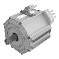
Powertrain
Brand: DANA
|
Category: Industrial Equipment
|
Size: 6 MB
Table of Contents
Advertisement
DANA TM4 SUMO MD MV Installation Manual (42 pages)
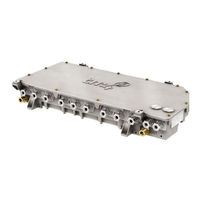
Motor Control Unit
Brand: DANA
|
Category: Automobile Accessories
|
Size: 1 MB
Table of Contents
DANA TM4 SUMO MD MV Installation Manual (42 pages)
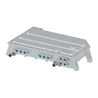
Motor Control Unit
Brand: DANA
|
Category: Control Unit
|
Size: 1 MB
Table of Contents
Advertisement
Advertisement