Sign In
Upload
Manuals
Brands
Daikin Manuals
Chiller
AWV018
Daikin AWV018 Manuals
Manuals and User Guides for Daikin AWV018. We have
1
Daikin AWV018 manual available for free PDF download: Installation, Operation And Maintenance Manual
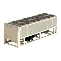
Daikin AWV018 Installation, Operation And Maintenance Manual (93 pages)
Air-cooled Screw Chillers 100 to 565 Tons (350 to 1985 kW) HFC-134a Refrigerant 60/50 Hz
Brand:
Daikin
| Category:
Chiller
| Size: 7.51 MB
Table of Contents
Table of Contents
2
Pre-Start Checklist – Screw Chillers
3
Introduction
5
General Description
6
Nomenclature
6
Operating Limits for AWV Chillers
6
Nameplates
7
Receiving and Handling
7
Unit Placement
7
AWV Unit Rigging
7
Installation and Application Considerations
7
Spacing Guidelines for Sufficient Airflow
8
Service Access
8
Mounting Hole Access
8
Clearance Requirements
8
Building or Wall on One Side of Unit
9
Case 1 for AWV 008-010 Models
9
Two Units Side-By-Side
10
Three or more Units, Side-By-Side
11
Open Screening Walls
12
Pit/Solid Wall Installation
12
Allowable Wall Open Area
12
Pit Installation
12
Chilled Water Piping
14
Typical Chilled Water Piping, Braze Plate
14
Typical Chilled Water Piping, Shell and Tube Evaporator
14
Installing Inlet Strainer (Field-Installed Kit)
15
Strainer Sizing Data
15
System Water Volume
15
Inlet Strainer Guidelines
15
Flow Switch
16
Evaporator Freeze Protection
16
Chilled Water Pump
16
Variable Speed Pumping
17
Ice Mode
17
Glycol Solutions
17
Electrical Connections
17
Use with On-Site Generators
18
Generator Sizing
18
Transfer Back to Grid Power
18
Long Term Storage
18
Field Wiring Diagram - Single Point Power
19
Field Wiring Diagram - Multiple Point Power
20
Remote Evaporator Refrigerant Piping
25
Shipment Method
25
Performance Data
25
Remote Evaporator Field Wiring Notes
26
Piping Layout
26
Remote EXV Field Wiring
26
Piping Schematic, Remote Evaporator (One of Two Circuits)
27
Sizing Guidelines for Horizontal
28
Downflow Suction Lines and Liquid Lines
28
Recommended Horizontal or Downflow Suction Line Size
29
Recommended Liquid Line Size
29
Evaporator Data for AWV Remote Evaporator Models
32
Evaporator Model EV4027
32
Dimensions - Remote Evaporators
32
Evaporator Model EV5027
33
Evaporator Model EV5039
33
Evaporator Model EV6639
34
Evaporator Model EV6633
34
Reference Dimensional Drawing
35
Unit Dimensions by Configuration with Braze Plate Evaporator
35
Unit Dimensions by Configuration with Shell and Tube Evaporator
37
Isolator Installation
38
Rubber-In-Shear Isolator Schematic
38
Spring Isolator - 2 Spring Schematic
38
Mounting Location Reference Drawing
38
Evaporator Flow Limits
39
Pressure Drop Data
39
Operator Responsibilities
42
Operator Schools
42
Software Version
42
Controller Features
42
Controller Operation
42
System Architecture
43
Modbus Communication - Unit
43
Microtech III Inputs/Outputs
44
Economizer EXV Module
45
Alarm/Limit Module
45
Compressor Vfds
45
Rapidrestore Module
45
Set Points
46
Unit Level Set Points
46
Set Point Default and Range
46
Dynamic Set Point Ranges
48
Unit Test Mode Set Points
48
Administration and Service Support
48
Cool LWT Set Point Ranges
48
Fan VFD Configuration
49
Fan Staging Deadbands
49
Circuit Level Set Points
49
Circuit Test Mode Set Points
50
Calculations
51
Evaporator
51
Unit Enable
51
Unit Functions
51
Unit Control States
52
Unit Status
52
Unit Status Conditions
52
Ice Mode Start Delay
53
Low Ambient Lockout
53
Lockout and Stop Operation
53
Lockout Only Operation
53
Leaving Water Temp (LWT) Reset
54
Pump Selection
54
Primary/Standby Pump Staging
54
Freeze Protection
54
Unit Capacity Control
55
Maximum Circuits Running
55
Cool Mode Operation
55
Staging Sequence
55
Unit Capacity Limits
56
Demand Limit
56
Network Limit
56
Load Balancing
56
Operation Following Cycling of Power
57
Unit Level Changes
57
Circuit Level Changes
57
Feedback Capacity
58
Approach Values
58
Superheat Values
58
Circuit Functions
58
Circuit Availability
59
Circuit States
59
Oil Sump Check
59
Circuit Status
60
Compressor Control
60
Run Command Output
60
Cycle Timers
60
Condenser Fan Control
61
VR Solenoid Valve Control
61
Physical Fan Layout
61
Manual Speed Control
61
Saturated Condenser Temp Target
62
Minimum Target Value
62
Condenser Fan Control State
62
Fan Control – no VFD or 1St Fan VFD
62
Fan Outputs Per Fan Stage
63
Staging Concept
63
Staging up
63
Digital Outputs Energized for each Stage
63
VFD on 1St Fan of each Circuit
64
Fan Control - All Fans with VFD
64
Normal Control
64
Stage up Compensation
64
Evaporator EXV Control
65
Closed State
65
Preopen Operation
65
Pressure Control State
65
Operation – Closed State
66
Superheat Control State
66
Economizer EXV Control
66
MOP Control State
66
Liquid Line Solenoid Valve
67
High Water Temperature Capacity Limit
67
Circuit Capacity Overrides
67
Alarm Logging
68
Signaling Alarms
68
Clearing Alarms/Faults
68
Description of Alarms
68
Alarms and Events
68
Evaporator Water Temperatures Inverted
69
Evaporator LWT Sensor Fault
69
Evaporator Water Freeze Protect
69
Evaporator Flow Loss
69
OAT Sensor Fault
70
External Alarm
70
Emergency Stop
70
Evaporator EWT Sensor Fault
70
Circuit Alarms
71
Evaporator Pump #1 Failure
71
Economizer EXV Module Comm Failure
71
Bad Demand Limit Input
71
High Condenser Pressure
72
Low Pressure Difference or Ratio
72
Mechanical Low Pressure Switch
72
Mechanical High Pressure Switch
72
High Motor Temperature
73
Compressor Multiple Start Failure
73
High Oil Pressure Difference
73
High Discharge Temperature
73
Low Discharge Superheat
74
High Motor Current
74
High Compressor VFD Current
74
Compressor VFD Temperature High
74
CC Module Comm Failure
75
EEXV Module Comm Failure
75
Evaporator Pressure Sensor Fault
75
Condenser Pressure Sensor Fault
75
Discharge Temperature Sensor Fault
76
Evaporator EXV Motor Error
76
Power Loss While Running
76
Failed Pumpdown
76
Low Evaporator Pressure - Unload
77
Low Evaporator Pressure - Hold
77
DC Fan Motor Fault
77
Events
77
Low Pressure Difference or Ratio Shutdown
78
High Motor Current – Hold
78
High Motor Current - Unload
78
High VFD Line Current Hold
78
High VFD Temperature Hold
79
High VFD Temperature Unload
79
Compressor Start Failure
79
Unit Controller Operation
80
Navigating
80
Passwords
80
Typical Screen
80
Using the Controller
80
Example of Screen Menu
81
Navigation Mode
81
Edit Mode
81
HMI Keypad Navigation
82
Pre-Startup
83
Temporary Shutdown
83
Startup after Temporary Shutdown
83
Startup and Shutdown
83
Startup after Extended (Seasonal) Shutdown
84
Vibration Monitoring (Optional)
85
Lubrication
85
Oil Filter Removal and Renewal
85
System Maintenance
85
Oil Filter Housing Cover Plate
86
Fitting a New Oil Filter Element – Reassembly
86
All-Aluminum Condenser Coils
86
Electrical Terminals
86
Cleaning Microchannel Aluminum Coils
87
Remove Surface Loaded Fibers
87
Cleaning Epoxy Coated Coils
87
Routine Quarterly Cleaning of Epoxy Coil
87
Liquid Line Sight Glass
88
Lead-Lag
88
Pump Operation
88
Harsh Chemical and Acid Cleaners
88
Preventative Maintenance Schedule
89
Definitions
90
Active Set Point
90
Active Capacity Limit
90
Deadband
90
Appendix
90
Advertisement
Advertisement
Related Products
Daikin AWV008
Daikin AWV012
Daikin AWV014
Daikin AWV016
Daikin AWV020
Daikin AWV024
Daikin AWV026
Daikin AWV030
Daikin AWV010
Daikin AGZ 055D
Daikin Categories
Air Conditioner
Heat Pump
Remote Control
Chiller
Fan
More Daikin Manuals
Login
Sign In
OR
Sign in with Facebook
Sign in with Google
Upload manual
Upload from disk
Upload from URL