Sign In
Upload
Manuals
Brands
Daihatsu Manuals
Automobile
G200
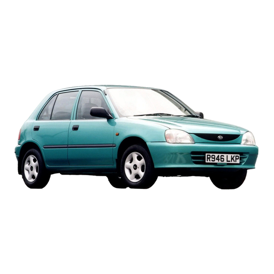
Daihatsu G200 Compact Car Manuals
Manuals and User Guides for Daihatsu G200 Compact Car. We have
1
Daihatsu G200 Compact Car manual available for free PDF download: Service Manual
Daihatsu G200 Service Manual (486 pages)
Brand:
Daihatsu
| Category:
Automobile
| Size: 11 MB
Table of Contents
Important Safety Notice
2
Warnings, Cautions and Notes
2
Chassis Serial Number Stamped Position
3
Plate Position
3
Contents of Plate
3
Engine Number and Engine Type Stamped Positions
4
CB Engine
4
CB Engine for Autstralian Specifications
4
Body Color Information
5
Color Code in the World
5
Trim Code
5
Vehicle 4-Plan Diagrams
6
4-Plane Diagram of 3-Door Model
6
Performance Diagrams
8
Engine Specification
10
Power Train Specifications
13
Lamp Specifications
16
Main Service Specifications
17
Main Modification Points Compared with Former Model
19
Engine
20
Body
21
Safety
21
Collision Safety
21
Transverse Collision Safety
21
Employment of Lock Reinforcement
22
Fuel Inlet Box
22
High Mount Stop Lamp
22
Rear Wiper
22
Easy Operation
23
Inside Rear View Mirror
23
Improvement of Door Closing
23
Weight Reduction
23
Quietness
24
Quarter Window Glass
24
Bell Crank for Rear Door
24
Blow-Molding Protection Molding
24
High-Rigidity Cab
25
Front Pillar
25
Rear Pillar
25
Center Pillar
25
Dash Crossmember
26
Instrument Panel Reinforcement
26
Rocker Panel
26
Wheel House Brace
26
Floor Tunnel Reinforcement
27
Floor under Reinforcement
27
Top of Rear Pillar
27
Increased Rigidity of Door Frame
28
Employment of Door Sash Having Large Section
28
Engine Mountings
29
Engine Mounting Right Insulator
29
Engine Mounting Left Insulator
30
Engine Mounting Rear Insulator
30
Engine Mounting Front Insulator
30
Silencer
32
Improvement of Appearance Quality
33
Back Door Glass
33
Door Outside Panel
33
Side Outer Panel
33
Others
34
Canvas Top
34
Opening/Closing of Canvas Top
34
Front Door Glass Holder
35
Rear Seat Hip Point
35
Opening/Closing in Event of Switch Failure
35
Power Train
36
Clutch
36
Clutch Disc
37
Clutch Cover
37
Control Mechanism
38
Clutch Release Bearing
38
Clutch Release Fork
38
Manual Transmission
39
Transmission Case
39
4-Speed Electrically-Controlled Transmission
40
Construction
41
Cross Section View
41
Carburetor Spec.
41
EFI Spec
41
System Diagram
42
Hydraulic System
42
Suspensions
43
Rear Suspension
44
Steering System
45
Steering Gear Assembly
46
Manual Steering Gear Assembly
46
Power Steering Gear Assembly
46
Specifications
46
Steering Wheel
47
Resin-Made Steering Wheel
47
Foamed Urethane-Made Steering Wheel
47
Steering Column
48
Power Steering Vane Pump
49
Reservoir Tank
50
Tie Rod Ends
50
Reservoir Tank Specifications
50
Brakes
51
Brake Master Cylinder
52
Brake Booster
53
Proportioning Valve
54
Front Brake
55
Rear Brake
56
Disc Rotor
57
Abs
57
Parking Brake Mechanism
58
One-Shot Mechanism
58
Parking Brake
59
Vehicle Interior
60
Instrument Panel
61
Console Box
62
Air Conditioner
63
Wheel
64
Wheel Cap
64
Maintenance
65
Maintenance Schedule
66
Section Description
66
Maintenance Operations
69
Brake Pedal
69
Free Play
69
Reserve Travel
69
Brake Fluid
70
Effectiveness
70
Level
70
Air Bleeding
70
Brake Hose & Tube
71
Leakage, Loose Clamp and Damage
71
Hose Change
71
Parking Brake Lever
72
Working Travel
72
Parking Brake Rod & Cable
73
Tightness, Rattle or Damage
73
Disc Brake Pad Wear
75
Cup and Dust Seal Replacement
75
Disc to Pad Clearance
77
Fluid Leakage
77
Rear Drum Brake
78
Brake Drum and Lining Wear
79
Wheel Cylinder Replacement
79
Drum to Lining Clearance
81
Rear Disc Brake
82
Ignition Check
89
Brake Booster Removal
89
Replacement of Rubber Parts
90
Brake Booster Push Rod Clearance Adjustment
95
Brake Booster Installation
96
Removal of Brake Master Cylinder
98
Inner Parts Replacement
98
Fuel Hose and Check Valve
101
Fuel Tank Removal
102
Function Check of Check Valve
103
Fuel Tank Installation
103
Chassis Grease & Oil
104
Door & Hood
104
Lock Operation
104
Muffler and Exhaust Pipe
104
Seat Belts
105
Battery
105
Connection of Terminal Section
105
Specific Gravity
105
Horn, Wiper, Windshield Washer & Defroster
106
Lighting System
106
Wiper Switch
106
Light Control Switch
106
Dimmer Switch and Passing Light
107
Turn Signal Switch
107
Hazard Warning Signal Switch
107
Room Lamp
107
Meter & Gauge
108
Wire Harness
108
Speedometer
108
Tachometer
108
Automatic Transmission
109
Fluid Level
109
Fluid Change
109
Oil Leakage
111
Oil Change
111
Rattle of Operation Mechanism
111
Drive Shaft
112
Joint Dust Boot
112
Connecting Section
112
Joint Sections
112
Clacks and Damage
113
Objects Caught in the Tire Pattern
113
Pressure
113
Wear
113
Wheel Disc
114
Wheel Hub Nuts
114
Wheel Bearing
114
Steering Ball Joint Dust Boot
115
Gear Box
115
Knuckle
115
Power Steering Belt
115
Tightness
116
Power Steering Fluid
116
Fluid Hose Change
116
Tie Rod and Arm
118
Wheel Alignment
119
Side Slip Test
119
Turning Angle
119
Correction of Wheel Turning Angle
119
Suspension & Linkage
120
Shock Absorber
120
Suspension Arm, Control Arm & Dust Cover
120
Maintenance Requirements
122
Cold Engine Operation
125
Inspection of Engine Coolant Level
125
Inspection of Radiator Cap and Radiator Filling Port
125
Inspection of Engine Coolant Leakage
126
Inspection of the Battery
127
Check of Specific Gravity of Battery Electrolyte
128
Inspection of Battery Electrolyte Level
128
Inspection of Drive Belt
129
Inspection of the Drive Belt Tension
130
Adjustment of Drive Belt Tension
130
Inspection Air Filter Element
131
Removal of Air Filter Element
131
Replacement of Air Filter Element
131
Cleaning of Air Filter Element
131
Inspection of Blow-By Gas Recirculation Device
132
Installation of the Air Filter Element
132
Inspection of Heat Preventive Device
133
Inspection of the Spark Control System
133
Inspection of the Fuel Line and Connection
135
Replacement of Fuel Filter
136
Inspection of Fuel Evaporative Emission Control Device
138
Inspection of the Charcoal Canister
139
Inspection of Outer Vent Valve
140
Inspection of the BVSV
140
Inspection of the Fuel Filter Cap
141
Inspection of Throttle Valve
143
Inspection of Choke Valve
144
Inspection of Carburetor Linkage
144
Replacement of Timing Belt
145
Removal of Air Conditioner Drive Belt
145
Installation of Timing Belt
149
Installation of Timing Belt Cover
152
Installation of Crankshaft Pulley
152
Hot Engine Operation
155
Inspection of Engine Oil
155
Change of Engine Oil and Oil Filter
156
Inspection of Engine Starting and Abnormal Noise
158
Inspection of Spark Plug
158
Removal of the Spark Plug
159
Visual Inspection of Spark Plug
159
Inspection of Electrode Gap
159
Inspection of Spark Plug Insulation Resistance
159
Inspection of Distributor Cap and Rotor
160
Installation of Spark Plug
160
Connect the Resistive Cords to the Spark Plug
160
Inspection and Adjustment of Valve Clearances
161
Removal of Cylinder Head Cover
162
Installation of Cylinder Head Cover
164
Inspection and Adjustment of Ignition Timing
165
Adjustment of Ignition Timing
167
Inspection and Adjustment of Idle Speed
170
Connection of Tachometer
171
Inspection and Adjustment of Throttle Positioner of Dashpot
172
Inspection and Adjustment of CO/HC Concentrations
175
Checking of CO/HC Concentrations
177
Change of Coolant
178
Coolant Capacity
179
Introduction
184
Fuel System
184
Intake System
184
Control System
184
Precaution
185
Inspection Precautions
186
Maintenance Precautions
186
When the Vehicle Is Equipped with Wireless Installation
187
Air Induction System
187
Electronic Control System
187
Troubleshooting
191
System Description
193
Engine will Not Crank or Cranks Slowly
194
Engine will Not Start
194
Engine Stalls While Idling
195
Engine Idle Speed will Not Drop
196
Rough Idling
196
Poor Driveability
196
Diagnosis System
198
Check of "Check Engine" Warning Light
198
Output of Diagnosis Codes
198
Output of Diagnosis Code
199
Diagnosis Code
201
Canceling Diagnosis Code
202
Fail-Safe Function
203
Troubleshooting with Volt/Ohmmeter
204
Preparation of Trouble Shooting
204
Check Procedure for EFI System
204
Arrangement of Input/Output Terminals
205
Wiring Diagram
207
Ecu
208
Measurement of ECU Input/Output Voltage
208
Inspection of Terminal Voltage and Resistance of ECU
210
Voltage at ECU Connector
211
Measurement of Resistance of ECU
213
Resistance at ECU Terminal
213
Location of Electronic Control Parts
214
Inspection of ECU Circuit
215
Inspection of Diagnosis System Circuit
215
Main Relay
217
Inspection of EFI Main Relay
217
Check of Main Relay Operation
217
Inspection of Relay Continuity
217
Circuit Opening Relay
220
Inspection of Circuit Opening Relay
220
Check of Fuel Pump Operation
220
Water Temperature Sensor
221
Inspection of Relay Operation
221
Inspection of Water Temperature Sensor
222
Intake Air Temperature Sensor
224
Inspection of Intake Air Temperature Sensor
224
Throttle Position Sensor
226
Inspection of Throttle Position Sensor
226
Pressure Sensor
234
Inspection of Pressure Sensor
234
Measurement of Output Voltage of Pressure Sensor
234
Connection of SST
234
Check of Output of Pressure Sensor
235
Specified Valve
235
Idle-Up VSV No.1
238
Inspection of Idle-Up VSV No.1
238
Oxygen Sensor
244
Inspection of Oxygen Sensor
244
Unit Inspection of Oxygen Sensor
244
Inspection of Oxygen Sensor System
245
Ignition Monitor
249
Distributor
252
Speed Sensor
253
Starter Switch
254
Automatic Transmission Control System
255
Air Conditioner Switch
261
Fuel System Wiring Diagram
264
Check of Fuel Pressure
265
Removal of SST
265
Check of Fuel Leakage
267
Check of Fuel Flow Rate
268
Inspection of Pressure Regulator
270
Injectors
272
Check of Injector Operation
272
Measurement of Resistance of Injector
272
Inspection of Injector
273
Fuel Tank and Line
275
Inspection of Fuel Lines and Connections
276
Throttle Body
277
In-Vehicle Inspection
277
Check of Throttle Body
277
Check of Auxiliary Air Valve
277
Sst
278
Liquid Gasket
278
Function of E.C.U.
282
Shift Schedule
282
Look-Up Schedule
282
Throttle Pressure Control
282
N-D Squat Control
283
Reverse Inhibit
283
Over Drive out Operation
283
Driving Mode Selection
283
Emergency Mode
284
Shift Position Switch
284
Inhibition of Shifting from D Range to 2 Range
284
Location of Electronic Parts Where Are Used
285
System Components
286
Flow of Hydraulic Control and Electrical System
286
Test Running by Manual Shift
288
Preliminary Check
289
Check of Transaxle Fluid Level
289
Check of Engine Idling Speed
289
Transaxle Warming-Up Method
289
Check of Fluid Condition
290
Change of Transaxle Fluid
290
Examination of Particles
290
Check of Shift Lever Position
291
Adjustment of Control Cable
291
Adjustment of Neutral Start Switch
291
Driving Pattern
292
Inspection of Neutral Start Switch
292
A/T E.C.U. Unit Check
293
Instructions Prior to Work
293
Diagnosis Function
293
Diagnosis Signal Table
294
Terminal Distribution Table
295
Pre-Inspection
296
Electronic Parts Inspection through SST
298
Unit Inspection
304
Test Terminal
304
Key Interlock with Shift Lock Wiring Diagram
305
Shift Lock Electric Control Unit
305
Shift Lock E.C.U. Input/Output Specification
306
Hydraulic Control System
307
Testing
308
Stall Test
308
Measurement of Stall Speed
308
Evaluation
308
Time Lag Test
309
Measurement of Time Lag
309
Location of Test Plugs
310
Hydraulic Test
311
Measurement of 2Nd and 4Th Brake Applying Pressure
312
Road Test
313
R Range Test
314
P Range Test
314
2Nd Range
314
Low Range Test
314
Gear Shift Points Table
315
Table of Fail-Safe Functions
316
Functions of Gear Characteristic Table
316
Functions of each Gear Shift Control Element
316
Troubleshooting Table
317
Hydraulic Troubleshooting
318
On Vehicle Repair
321
Replacement of Oil Seal at Differential Side
321
Replacement of Oil Seal at the Gear Speedometer Driven
321
Replacement of Hose and Tube Oil Cooler Inlet / Outlet
322
Solenoid for Shift No.1, No. 2 and Pressure Control
323
Function of Solenoid
325
Sensors
325
Removal and Installation of Automatic Transmission
326
Prior to Work of Removal
326
Torque Converter
334
Installation
334
Components
346
Oil Pump Component
357
Disassembly of Oil Pump
357
Inspection of Oil Pump
357
Assembly of Oil Pump
358
Forward Clutch Components
359
Overdrive & Coast Clutches
363
Front and Rear Planetary Ring Gear
368
Operation Check of 1 Way Clutches
369
Reverse Clutch
374
Counter Driven Gear
379
Valve Body
382
Differential
387
Transaxle Housing
391
Transaxle Case
392
Harness & Wiring
407
General Information
408
Lock Type Connector
408
Disconnection
408
Tester
408
Terminal Removal/Installation
409
Conventional Type Connector
409
Water-Proof Type Connector
409
Housing Lance Type
409
Pun Number of Connector
410
Operation of Wire Harness
410
Installation of Terminal
410
Metal Lance Type
410
Terminals and Connectors
411
Wiring Harnesses
412
Wiring Color Code
412
Inspection of Circuit with Tester
413
Inspection of Short Circuit
413
Junction Block
414
Main Fuse Block
414
Fuse Check and Replacement
414
Schematic Diagram of Wiring Harnesses
415
Starter and Alternator
416
Ignition Coil and Idle up
417
Horn, Turn & Hazard and Back up Lamp
418
Mter
419
Wiper & Washer, Defogger and Heater
420
Day Light, Headlamp
421
Tail Lamp and Independent Tail Fuse
422
Courtesy Lamp, A/T Shift Lock and Stop Lamp
423
Power Window, Canvas Top and Door Lock
424
Engine ECU
425
4 A/T Ecu
426
Abs Ecu
427
Radio and Remote Control Mirror
430
Wire, Front Door RH
432
Advertisement
Advertisement
Related Products
Daihatsu 1978 Charade
Daihatsu 1997 Terios J100
Daihatsu F300
Daihatsu Mira
Daihatsu S85
Daihatsu TERIOS J100
Daihatsu Categories
Automobile
Engine
Trucks
Security Sensors
Door Opening System
More Daihatsu Manuals
Login
Sign In
OR
Sign in with Facebook
Sign in with Google
Upload manual
Upload from disk
Upload from URL