Sign In
Upload
Manuals
Brands
Curtiss-Wright Manuals
Measuring Instruments
D51615-202 Series
Curtiss-Wright D51615-202 Series Manuals
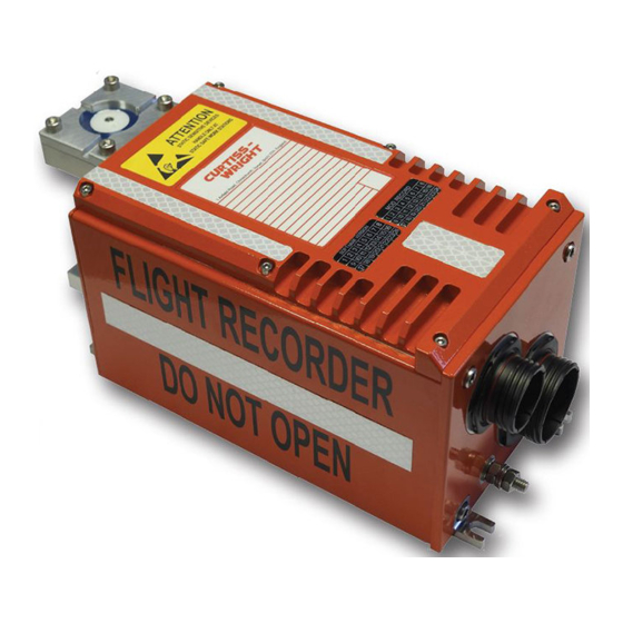
Manuals and User Guides for Curtiss-Wright D51615-202 Series. We have
1
Curtiss-Wright D51615-202 Series manual available for free PDF download: Manual
Curtiss-Wright D51615-202 Series Manual (127 pages)
Brand:
Curtiss-Wright
| Category:
Measuring Instruments
| Size: 2 MB
Table of Contents
Amendment Record
3
Table of Contents
5
Abbreviations and Symbols
12
Introduction
17
Day Beacon Kit
17
Dafr Type
17
Part 1: Data Acquisition Flight Recorder
19
Description, Operation and Specification
19
Description
19
General
19
Equipment Part Numbering
21
Mechanical Description
22
Electrical Description
22
Interface Description
23
Table 1 Aircraft Matingc
24
Figure 5 Installation Drawing for
25
Operation
34
Operational Modes
34
Specification
38
Functional Characteristics - Performance
38
Physical and Other Characteristics
46
Environmental Conditions
46
Table 3 Non -Cockpite
47
Table 4 Aircraft Fluids
48
Storage
50
Unpacking
50
Installation
51
Installation Approval
51
System Design
51
Figure 8 Typical Dafr System
52
Figure 9 Typical Wiringd
53
Signal Levels
55
Wiring
55
Power Supply
56
Termination of Recording
56
Start of Recording
56
Voice Erase
57
Recorder Location
57
Mounting
57
Post Installation Check
58
Continuity Check
58
System Check
58
Flight Test
58
Operating Instructions
59
DATA ACQUISITION FLIGHT RECORDER Type D51615-202-XXX or D51615
59
202-XXX-090 with CCU Type D51616-XXXX and CAM Type D51623-XXXX
59
Installation and Operating Manual with Illustrated Parts List
59
General
59
Controls and Indicators
59
TEST Pushbutton
59
ERASE Pushbutton
60
FDR RCRD Switch (FDR INHIBIT)
60
CVR FAIL Indicator
60
FDR FAIL Indicator
60
Headphone Jack
60
Maintenance
61
General
61
Dafr Periodic Maintenance Tasks
61
Table 5 Maintenance Tasks for Table 6 Beacon Voltagec
62
Functional Check
63
Procedure
63
Ulb Periodic Inspections
63
ULB Switch Cleaning
63
ULB Battery Test
63
ULB Test
65
Figure 10 Typical Beaconl
65
ULB Removal and Replacement (30-Day Beacon Battery)
66
ULB Removal and Replacement - 90-Day Beacon
67
Cvr System Check
68
Equipment Required
68
Procedure
68
Fdr System Check
69
Equipment Required
70
Procedure Using Internet Explorer
71
Procedure Using PGS Only
74
Cvr Replay
76
Equipment Required
76
Procedure Using Internet Explorer
77
Procedure Using
78
CVR Audio Analysis
79
Fdr Replay
80
Equipment Required
80
Procedure
80
Inspection
81
Testing and Fault Isolation
82
General
82
Part One (Verification)
82
Test Equipment Requirements
83
Default Mode of Operation - Current Status
83
Table 7 Special to Type Test
83
Table 8 General Purpose Test
83
Diagnostic Checks
84
Figure 11 Typical Statusp
85
Part Two (Fault Isolation)
86
General
86
Figure 12 Fault Isolationf
87
Figure 13 Fault Isolationf
88
Cleaning
89
Materials
89
General Cleaning
89
Ulb Switch Cleaning
89
Table 9 Cleaning Materials
89
Repair
90
Illustrated Parts List
91
202-XXX-090 with CCU Type D51616-XXXX and CAM Type D51623-XXXX
91
Installation and Operating Manual with Illustrated Parts List
91
Introduction
91
General
91
Equipment Designator Index (When Applicable)
91
Numerical Index (When Applicable)
91
Detailed Parts List
91
Figure 15 Data Acquisition
96
Figure 14 Data Acquisition
101
Part 2: Cockpit Control Unit
102
Description, Operation and Specification
102
Description
102
General
102
Figure 16 Cockpit Control
102
Mechanical Description
103
Operation
103
Interfaces
103
Figure 17 Cockpit Control
103
Table 10 Cockpit Controlu
104
Table 11 Cockpit Controlu
105
Installation
106
Equipment Inputs
106
Equipment Outputs
108
Specification
109
Functional Characteristics - Performance
109
Physical and Other Characteristics
109
Figure 18 Cockpit Control
110
Environmental Characteristics
111
Storage
112
Unpacking
112
Table 12 : Cockpit Equipment
112
Installation
113
Wiring
113
Signal Levels
113
Power Supply
114
Figure 19 Cockpit Control
115
Figure 20 Cockpit Control
116
Maintenance
117
Repair
117
Fault Finding
117
Description, Operation and Specification
118
Description
118
Operation
118
Specification
118
Functional Characteristics - Performance
118
Physical and Other Characteristics
118
Compatibility/Interfaces
119
Cam Part Number
119
D51702 Part
119
Installation
120
Wiring
120
Cam Location
120
Table 13 Microphone Cable
120
BONDING (Recommended)
121
Figure 23 Installationd
122
Figure 24 Installationd
123
Figure 25 Preferredl
123
Storage
124
Figure 26 Microphones
124
Unpacking
125
Maintenance
125
Repair
125
DATA ACQUISITION FLIGHT RECORDER Type D51615-202-XXX or D51615- 202-XXX-090 with CCU Type D51616-XXXX and CAM Type D51623-XXXX
126
Installation and Operating Manual with Illustrated Parts List
126
Advertisement
Advertisement
Related Products
Curtiss-Wright D51600
Curtiss-Wright DTS1
Curtiss-Wright DTI-VME/S
Curtiss-Wright DuraDBH-672
Curtiss-Wright DUCOR-80-40-00
Curtiss-Wright DUCOR-80-40-10
Curtiss-Wright DUCOR-80-40-20
Curtiss-Wright DTS1+ CSfC
Curtiss-Wright KAD/ADC/129/S2
Curtiss-Wright SSR/CHS/001
Curtiss-Wright Categories
Computer Hardware
PCI Card
Controller
Switch
Measuring Instruments
More Curtiss-Wright Manuals
Login
Sign In
OR
Sign in with Facebook
Sign in with Google
Upload manual
Upload from disk
Upload from URL