Sign In
Upload
Manuals
Brands
Curtiss-Wright Manuals
Storage
DTS1
Curtiss-Wright DTS1 Manuals
Manuals and User Guides for Curtiss-Wright DTS1. We have
1
Curtiss-Wright DTS1 manual available for free PDF download: User Manual
Curtiss-Wright DTS1 User Manual (141 pages)
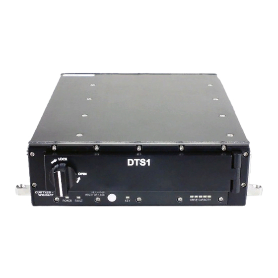
CSfC / ECC Cryptographic Data Transport System
Brand:
Curtiss-Wright
| Category:
Storage
| Size: 6 MB
Table of Contents
Front Matter
3
Safety
4
Style and Conventions
5
Table of Contents
6
List of Figures
11
Table of Contents
11
List of Tables
12
Introduction
13
Quality
13
Ordering Process
14
Technical Support
14
Overview
15
Description
15
Chassis
15
Figure 2.2 DTS1 Chassis / Components
16
Figure 2.7 Hardware Encryption Layer Account Login
20
Chassis Indicators
23
Controls and Indicators
23
Fault Led
23
Power Led
23
Chassis Controls
24
Key Clear Button
24
RMC Module Controls / Indications
24
Write-Enable Switch
24
ACTIVITY LED (Green / Middle)
25
Removal Request Button
25
RMC Module STATUS LED Indications
25
Inspection
26
Installation
26
DTS1 Rear Panel / Battery Access Cover and Rear Connectors
17
DTS1 with RMC Module
17
RMC Module
17
Account Creation
18
Csfc Encryption
18
Hardware Encryption Layer
18
Protocols
18
Account Login
19
Hardware Encryption Layer Account Creation
19
Features
20
Software Encryption Layer
20
Zeroize
20
Figure 4.1 DTS1 Chassis Anti-Tamper Label Locations
26
DTS1 Chassis Mounting
27
Figure 4.2 RMC Module Anti-Tamper Label Location
27
Figure 6.1 Initialization Quick Start Process Flow
48
Login
49
Login Quick Start Process Flow
50
Operation
51
Cables
28
DTS1 Rear Panel Connectors
28
DTS1 Required Door Clearance
28
Power Cable
28
Ethernet Cable
29
Utility Cable
29
Utility Lab Cable
29
DTS1 Ground Connection
30
Ground Cable
30
Encryption
31
Hardware Layer Passwords
31
Passwords / Passphrases
31
Software Layer Passwords / Passphrases
31
Check Hardware Layer Status
32
Hardware Layer Definitions
32
Hardware Layer Encryption
33
Hardware Encryption Key Storage
35
Autoload Key
37
Load / Unload Stored Hardware Encryption Key to RMC Module
37
Software Layer Encryption
38
Unpartitioned Disk
38
Close SWE Container (Unpartitioned Disk)
39
Format / Mount SWE Container (Unpartitioned Disk)
39
Open SWE Container (Unpartitioned Disk)
39
Delete SWE Container (Unpartitioned Disk)
40
Partitions
40
Initialize SWE Encryption (Partitions - same Passphrase)
42
Zeroize HWE Key / Delete SWE Container / RMC Purge
45
Connections / Preparation
47
Initialization
47
Quick Start
47
Figure 2.1 DTS1
51
Figure 7.1 DTS1 Test Setup
51
Figure 7.3 Putty Terminal Emulator (SSH)
53
Account Management
54
IP Address
54
Passwords
54
Time / Date
55
Storage Media
56
Partition Disk
57
Assign Services
58
Services
58
Boot Services
59
Restart Services
59
Assign Mount Point Names
60
Format / Mount
61
Format Only
61
Example of RMC Module Status
62
Pcap
65
Health
66
Sens
66
Built in Test
67
IBIT (Initiated BIT)
67
MBIT (Maintenance BIT)
67
Update Software / Firmware
68
Access from Windows as NAS Device
69
DTS1 Update Utility
69
Access from Linux as NAS Device
70
Crypto Module
71
Dts1
71
Key Commands
71
System Configuration
71
RMCCTL Definitions
72
Chassis LED Fault Indicators
74
Troubleshooting
74
Encryptor Error Codes
75
Simple Network Management Protocol
77
Snmp Mib
77
Basic Operation
52
Communications
52
Putty Terminal Emulator (Serial Data)
52
Terminal Emulation
52
Ethernet
53
Figure 11.1 RMC Module Install / Remove
80
Figure 11.2 RMC Module Controls, Indicators, and Handle
81
Figure 11.3 Battery Assembly Replacement
82
Figure 11.4 Battery Access Panel Screws Tightening Sequence
82
Command Line Interface
83
Cmkey
87
Cmlogin
90
Fwall
96
Help
98
Example: IBIT Execution
99
Ibit
99
Info
100
Ipconfig
102
Istarget
104
Ledctrl
106
Log
107
Ntpdate
110
Reboot
114
Rmcctl
115
Rmcfree
118
Rmcinfo
119
Rmcpurge
121
Rtp
122
Envelope / Mounting Dimensions
129
Specifications
129
Panel Mount
130
DZUS Fastener Mount
131
Table A.1 DTS1 / RMC Calculated Mean Time between Failures
132
RMC Module Specifications
132
DTS1 Specifications
132
DTS1 / RMC Calculated Mean Time between Failures
133
Connectors / Cables
135
Power Connector J1 / Power Lab Cable
135
Power Lab Cable (VS-DTS1PWRCAB-0)
135
Table B.1 Power Connector J1 Signals
135
Utility Connector J2 / Utility Lab Cable
136
Table B.3 Utility Connector J2 Signals
136
Ethernet Connector J3 / Ethernet Lab Cable
137
Utility Lab Cable (VS-DTS1ETHCAB-J2)
137
Figure B.3 Utility Connector J2
137
Figure B.4 Utility Lab Cable Diagram
137
Table B.5 Ethernet Connector J3 Signals
138
Table B.6 Ethernet Lab Cable (VS-DTS1ETHCAB-J3
138
Ground Lug
139
Ordering Information
140
Table C.1 DTS1 Csfc Chassis
140
Table C.2 RMC Module
140
Table C.3 DTS1 Lab Cables
140
Table C.4 DTS1 Battery
140
Figure A.1 RMC Module
140
Advertisement
Advertisement
Related Products
Curtiss-Wright DTI-VME/S
Curtiss-Wright D51615-202 Series
Curtiss-Wright DuraDBH-672
Curtiss-Wright DUCOR-80-40-00
Curtiss-Wright DUCOR-80-40-10
Curtiss-Wright DUCOR-80-40-20
Curtiss-Wright D51600
Curtiss-Wright DTS1+ CSfC
Curtiss-Wright VS-DTS1SL-F
Curtiss-Wright VS-DTS1SL-FD
Curtiss-Wright Categories
Computer Hardware
Controller
PCI Card
Switch
Measuring Instruments
More Curtiss-Wright Manuals
Login
Sign In
OR
Sign in with Facebook
Sign in with Google
Upload manual
Upload from disk
Upload from URL