Sign In
Upload
Manuals
Brands
Cornelius Manuals
Beverage Dispenser
REMCOR R-134A
Cornelius REMCOR R-134A Manuals
Manuals and User Guides for Cornelius REMCOR R-134A. We have
3
Cornelius REMCOR R-134A manuals available for free PDF download: Installation & Service Manual, Operator's Manual
Cornelius REMCOR R-134A Installation & Service Manual (54 pages)
VENTURE POST- MIX DISPENSER W/BUILT-IN COLD CARBONATOR (R- 134A REFRIGERANT)
Brand:
Cornelius
| Category:
Beverage Dispenser
| Size: 1.07 MB
Table of Contents
Table of Contents
2
Safety Information
5
Recognize Safety Information
5
Understand Signal Words
5
Follow Safety Instructions
5
Co2 (Carbon Dioxide) Warning
5
Shipping, Storing, or Relocating Unit
5
General Information
8
General Description
8
Unit Description
8
Figure 1. Venture Six-Flavor Post-MIX Dispenser
8
Warranty Reference Information
9
Table 1. Design Data
9
Theory of Operation
10
Figure 2. Flow Diagram (Five-Flavor Unit with Built-In Cold Carbonator)
11
Figure 3. Flow Diagram (Six-Flavor Unit with Built-In Cold Carbonator)
12
Installation
14
Unpacking and Inspection
14
Identification of Loose-Shipped Parts
14
Table 2. Loose-Shipped Parts
14
Selecting Location
15
Installing Water Only Lever Kit (P/N 3297) on Uf-1 Dispensing Valve
15
Installing Unit
15
Cutting Hole in Countertop
15
Connecting Plain Water Source Line(S) to Unit
15
Figure 4. Syrup Inlet Supply Line Connections (Six-Flavor Unit Shown)
16
Connecting Syrup Source Lines to Unit
17
Connecting Co2 Source Line to Unit
18
Sealing Unit Base to Countertop
18
Preparing Unit for Operation
18
Fill Water Tank and Start Refrigeration System
18
Unit Operation
19
Adjust Water-To-Syrup " Ratio"(Brix) of Dispensed Product
20
Operator' S Instructions
22
Operating Controls
22
Dispensing Valve Lever
22
Dispensing Valve with Water Lever
22
Dispensing Valves Keyed Lock-Out Switch
22
Unit Power Switch (115 Vac, 60 Hz Units Only)
22
Carbonator Water Pump Motor Power Switch
22
Daily Pre-Operation Check
22
Unit Operation
23
Adjustments
23
Adjusting Co2 Regulators
23
Adjusting Dispensing Valve Water Flow Rate
23
Adjusting Water-To-Syrup " Ratio"Of Dispensed Product
23
Replenishing Co2 Supply
23
Replenishing Syrup Supply
23
Cleaning and Sanitizing
23
Daily Cleaning of Unit
23
Sanitizing Syrup Systems
24
Checking Drop-In Refrigeration Assembly Condenser Coil for Restrictions
24
Checking Ice Water Bath
24
Carbonator Water Pump Yearly Maintenance or after Water
24
System Disruptions
24
Cleaning Co2 Gas Check Valves
24
Service and Maintenance
26
Preparing Unit for Shipping, Storing, or Relocating
26
Hood and Front Panel Removal
26
Hood Removal
26
Front Access Panel Removal
26
Periodic Inspection
26
Adjustments
26
Adjusting Co2 Regulators
26
Figure 5. Dispenser Components
27
Adjusting Dispensing Valves Water Flow Rate
28
Figure 6. Sf-1 Dispensing Valve
28
Figure 7. Uf-1 Dispensing Valve
29
Adjusting Water-To-Syrup " Ratio"(Brix) of Dispensed Product
30
Cleaning Drop-In Refrigeration Assembly Condenser Coil
31
Checking Ice Water Bath
31
Cleaning Water Tank
32
Cleaning and Sanitizing
33
Daily Cleaning of Unit
33
Figure 8. Water Tank
33
Sanitizing Post-MIX Syrup Systems
34
Carbonator Water Pump Yearly Maintenance or after Water
36
System Disruptions
36
Replenishing Co2 Supply
38
Figure 9. Water Strainer Screen and Double-Liquid Check Valve
38
Replenishing Syrup Supply
39
Figure 10. Liquid Check Valve Assembly
39
Bag-In-Box Syrup System
40
Syrup Tank System
40
Syrup Flavor Change
40
Cleaning Co2 System Co2 Gas Check Valves
40
Figure 11. Co2 Gas Check Valve Assembly
40
Figure 12. Wiring Schematic for Electronic Ice Bank Control (Optional)
41
Figure 13. Wiring Diagram (50 and 60 Hz Unit with 1/3 H.p. Refrigeration Assembly)
42
Figure 14. Wiring Diagram (60 Hz Unit with 1/4 H.p. Refrigeration Assembly and Built-In Cold Carbonator)
43
Figure 15. Wiring Diagram (50 Hz Unit with 1/4 H.p. Refrigeration Assembly and Built-In Cold Carbonator)
44
Figure 16. Wiring Diagram (Sf-1 Dispensing Valve)
45
Figure 17. Wiring Diagram (Uf-1 Dispensing Valve)
45
Troubleshooting
47
Troubleshooting Post-MIX System System
47
Water-To-Syrup " Ratio"Too Low or too High
47
Adjustment of Dispensing Valve Syrup Flow Control Does Not Increase to Desired Water-To-Syrup " Ratio
47
Adjustment of Dispensing Valve Syrup Flow Control Does Not Decrease to Desired Water-To-Syrup " Ratio
48
Dispensed Product Carbonation too Low
48
But Foams in Cup or Glass
48
Dispensed Product Comes out of Dispensing Valve Clear but Foams in Cup or Glass
48
Dispensed Product Produces Foam as It Leaves Dispensing Valve
48
No Product Dispensed from All Dispensing Valves
49
Only Carbonated Water Dispensed
49
Only Syrup Dispensed
49
Troubleshooting Refrigeration System
50
Compressor Does Not Operate
50
Compressor will Not Stop after Sufficient Ice Bank Is
50
Bulb)
50
Produced. (Note: Ice Bank Should Just Cover Control Bulb)
50
Compressor Operates Continuously but Does Not Form Sufficient Ice Bank
51
Agitator Motor Not Operating
51
Warranty
52
Advertisement
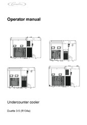
Cornelius REMCOR R-134A Operator's Manual (40 pages)
Undercounter cooler
Brand:
Cornelius
| Category:
Accessories
| Size: 3.8 MB
Table of Contents
Table of Contents
3
Safety
5
Intended Use
5
Improper Use
6
Staff
7
Operator
7
User
7
Expert
7
Presentation of Warnings
8
Safety Information
9
Disclaimer of Liability and Warranties
9
Safety Information to Prevent Personal Injury and Equipment Damage
10
Handling the Unit Prior to Installation
12
Unpacking the Unit
12
Storage
13
Disposal
14
Description
15
Assemblies and Components
15
Undercounter Cooler Duette 3 (R134A)
15
Undercounter Cooler Duette 4 (R134A)
16
Undercounter Cooler Duette 5 (R134A) Single
17
Undercounter Cooler Duette 5 (R134A) Dual
18
Functions Within the Dispensing System
19
Technical Data
20
Undercounter Cooler Duette 3 (R134A)
20
Undercounter Cooler Duette 4 (R134A)
21
Undercounter Cooler Duette 5 (R134A) Single/Duette 5 (R134A) Dual
22
Connections
22
Labelling Positions
23
Undercounter Cooler Duette 3 (R134A)
23
Undercounter Cooler Duette 4 (R134A)
23
Undercounter Cooler Duette 5 (R134A) Single/Duette 5 (R134A) Dual
23
CO 2 Working Pressures
24
Control and Indicator Panel
24
Cornelius REMCOR R-134A Operator's Manual (26 pages)
POST-MIX COOLING UNIT
Brand:
Cornelius
| Category:
Freezer
| Size: 0.36 MB
Table of Contents
Table of Contents
2
Safety Information
4
Recognize Safety Information
4
Understand Signal Words
4
Follow Safety Instructions
4
Co2 (Carbon Dioxide) Warning
4
Shipping, Storing, or Relocating Unit
4
General Information
6
Claims Instructions
6
Warranty Reference Information
6
Design Data
6
Description
7
Theory of Operation
8
Parts Identification
10
Owner' S Recommended Maintenance
12
Operators Instructions
14
Operating Controls
14
Cooling Unit Power Switch
14
Cooling Unit Circulating Pump Power Switch
14
Cooling Unit Carbonator Motor Power Switch
14
Daily Pre-Operation Check
14
General Maintenance
16
Adjustments
16
Adjusting Co2 Regulators
16
Adjusting Carbonator Water Tank Liquid Level
16
Sanitizing Syrup Systems
16
Checking Ice Water Bath
16
Cleaning Condenser Coil
17
Carbonator Water Pump Maintenance (or after Water System Disruption)
17
Replenishing Co2 Supply
17
Replenishing Syrup Supply
18
Periodic Cleaning of Cooling Unit
18
Cleaning and Sanitizing
18
Daily Cleaning of Unit
18
Sanitizing Post-MIX Syrup Systems
18
Troubleshooting
22
Dispensed Product Carbonation too Low
22
Only Syrup Dispensed
22
Warm Product Being Dispensed
22
Water Pump will Not Operate
22
Water Pump Motor Operates but Water Pump Does Not Pump Water
22
Water Pump Capacity too Low
22
Advertisement
Advertisement
Related Products
Cornelius R-404A REFRIGERANT
Cornelius R-454C
Cornelius Remcor TJ45-A
Cornelius Remcor TJ45-AB
Cornelius Remcor TJ90-A
Cornelius Remcor TJ90-AB
Cornelius Remcor TJ90-ABC
Cornelius Remcor TJ200
Cornelius Remcor TJ200A
Cornelius Remcor TJ200K
Cornelius Categories
Beverage Dispenser
Ice Maker
Dispenser
Accessories
Commercial Food Equipment
More Cornelius Manuals
Login
Sign In
OR
Sign in with Facebook
Sign in with Google
Upload manual
Upload from disk
Upload from URL