Sign In
Upload
Manuals
Brands
Copeland Manuals
Controller
E3
Copeland E3 Refrigeration Controller Manuals
Manuals and User Guides for Copeland E3 Refrigeration Controller. We have
4
Copeland E3 Refrigeration Controller manuals available for free PDF download: Installation And Operation User Manual, Quick Setup Manual, Quick Start Manual, Reference Card
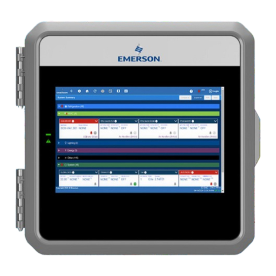
Copeland E3 Installation And Operation User Manual (241 pages)
Supervisory Control Platform
Brand:
Copeland
| Category:
Controller
| Size: 27 MB
Table of Contents
Table of Contents
3
Introduction
11
Supported Browsers
11
Security
11
Direct Connect Instructions - Connect Your Laptop to Supervisory Controller's Ethernet Port ETH 1
12
Logging into the Supervisory Controller
13
How to Change the IP Address
14
Method 1: Direct Connect
14
Method 2: USB Port
14
Setup Wizard
15
Uploading Certificate
17
E3 Hardware Overview
18
E3 Ordering Information
18
Technical Specifications
18
Plug-In Digital I/O Card (P/N 537-4880)
19
Led's
19
Wiring
19
Ethernet Connections
19
E3 RS485 Wiring Guide Example
20
E3 Wiring Diagrams
23
Site Supervisor Hardware Overview
26
Ordering Information
26
Technical Specifications
27
Site Supervisor Housing Dimensions and Mounting
28
Wiring Diagrams
29
Device Wiring
30
Site Supervisor Power, Serial, and IO Positions
30
Termination Jumpers
30
Using a DC Volt Meter to Check Termination and Bias
31
Removing the SD Card
31
Leds
31
Dip Switch Termination and Biasing
32
Serial Connections
33
Wiring Terminal Detail
33
Digital Inputs
34
Relay Outputs
34
Analog Inputs
35
Site Supervisor Wiring Examples
36
Supervisory Controller Basic Navigation
50
Menus and Submenus
50
Logical Groups
51
COM Port Bandwidth Color Scheme
52
COM Port Bandwidth Calculator
54
Overview
55
Conditional Visibility
55
User View Details
55
Basic Screen Elements
56
Language Settings
57
Locating and Working with Applications
57
Application Tabs
58
Performance Meter
58
Site Aggregation
58
Control Inventory
59
Adding Applications
59
Adfs
59
Creating a Backup and Restore
60
Backup
60
Encrypted Backup
60
Restore
61
Setting User Roles
61
Using the Help Menu
62
Icons or Buttons Appearing on the Home Screen
63
Logging Groups
65
Supported Functions
65
Data Logging Types
65
Logging Group Functions
65
Alarm Configuration
68
Alarm Communications
69
Alarm Communications Setting
70
Alarm Log and View History
71
Temperature Differential Alarms
71
Lighting Cycle Alarms
73
Smart Alarming
73
Accessing Smart Alarms
73
Peer Alarming
74
Generic Alarms
74
Alarm Types
74
Alarm Priorities/Filtering
75
Rs485 I/O Network Boards and Peripherals
76
The I/O Network
76
I/O Board Names and Terminology
76
Multiflex Boards
76
Multiflex 16 Input Board
76
Multiflex Combination Input/Output Boards
77
Multiflex CUB Support
78
Multiflex RTU Support
78
I/O Network and Multiflex RTU Setup on Serial Port
79
Creating an Instance of RTU Application
79
Deleting/Checking Status of RTU Board
79
Zone Management
79
Scheduling
79
Alarming
79
Real Time Clock Updates
80
Hand-Held Terminal Support
80
Multiflex RCB Support
80
I/O Network and Multiflex RCB Setup on Serial Port
80
Creating an Instance of RCB Application
80
Deleting/Checking Status of RCB Board
80
Zone Management
80
Scheduling
81
Alarming
81
Real Time Clock Updates
81
Hand-Held Terminal Support
81
Multiflex RTU
81
Multiflex Rooftop Control Board (RCB)
82
The Multiflex ESR Board
82
Hand-Held Terminal (P/N 814-3110)
82
The 8RO and 8ROSMT Relay Boards
83
4AO Analog Output Board
84
8DO Digital Output Board
84
XM Series of Case Controllers
84
XM670K V3.4
84
XM679K V3.4 and V4.2
85
XM678D V2.5 and V2.8
85
XEV22 V1.1 and V1.5
85
Wireless I/O
85
Site Supervisor Displays
86
Programmable Touchscreen Thermostat
87
Control Techniques Drive (VSD)
87
Dac
87
Copeland Discus with Coresense Diagnostics (ISD)
88
Copeland Discus with Coresense Protection
88
Copeland Scroll - K5 Refrigeration Compressor
88
Site Supervisor Displays
89
Display Connections
89
Specifications
90
Mounting Dimensions
90
Direct Connect to Site Supervisor
91
Inch Touchscreen Display
94
Display Connections
94
Specifications
94
Mounting Dimensions
95
Direct Connect to Site Supervisor
95
Site Supervisor Touchscreen Display Version Compatibility
96
Software Overview
97
Supervisory Controller Application and System Capacity Matrix
97
Site Aggregator Features
101
System Supervisor Features
102
Supervisory Controller Model Selection Guide
102
Supervisory Controller to E2 Cross-Reference Guide
103
Supervisory Controller New Features
104
Suction Groups
105
Introduction
105
The (Standard) Suction Group Application
105
Overview of PID Control Strategy
105
Variable-Speed Compressors
105
Floating Setpoint Control
105
The Enhanced Suction Group Application
106
Learning Mode
106
Circuit Load Analysis
106
The Control/Cycles Parameter
106
Variable-Speed, Digital Scroll, and Digital Discus Compressor Support
106
Floating Suction Control
106
Hardware Overview
107
Suction Float
107
Analog Sensor Control
107
Control Strategy
108
Control Alarming
108
Alarm Output When On/Off Parameters
108
Control Bypass
108
Digital Sensor Control
109
Control Strategy
109
Command Alarming
109
Alarm Output When On/Off Parameters
110
Control Bypass
110
Lighting Control
110
Lighting Control Logic
110
Light Level Sensor Verification
111
Solar Calculation
111
Digital Lighting Output
111
Light Proofing
111
Minimum On/Off Times
111
Dimming Control (Analog Output)
112
Theory of Operation
112
External Schedule
112
Lighting Bypass Inputs
113
Demand Shed Behavior
113
Global Data
113
Location from
113
Sundown
113
HVAC Control
113
Active Setpoint Determination
113
Setpoint Reset
114
Demand Shed
114
Heating and Cooling Control
114
Control Logic
114
Heat/Cool Lockout Based on Outside Air Temperature
115
System Shutdown
115
Fan Control
115
Fan Mode
115
Plenum Warmup/Purge
115
Fan Proof Failure
115
Economization (Damper) Control
116
Determine the Analog Damper Position
117
Determine the Digital Damper Position
117
Heat Pump Control
117
Reversing Valve
117
Compressor Output
117
Curtailment
117
Time Schedule Application
118
Time Schedule Method
118
Standard Schedule
118
Event Names
118
Maintenance Schedule
118
Maintenance Overrides
119
Holiday Schedules
120
Output Calculation
120
Scheduling Logic
120
Control Override
121
Control Bypass
121
Special Conditions
122
Priority of Services
122
Control Alarming
122
Schedule Category
122
Demand Control
122
KWH Calculation
122
Demand Calculation
123
Shed Outputs
123
Application Alarms
124
KW Load Specification
124
Performance Requirements
124
Utility Monitoring
124
Utility Usage Calculation
124
Utility Type
124
Electrical Usage
125
Consumption Totalizing
125
Fixed Period Totalizers
125
User Totalizer Output
125
Utility Logging Group
125
Demand Shedding
125
Overview
125
Average Rate of Consumption
125
Shed Output
125
Demand Limit Exceeded Alarm
126
Time in Shed Output
126
Onboard I/O
126
Licensing
126
Adding and Deleting Onboard I/O Application
126
Status and Detail Screen
127
Alarming
127
Xr75Cx 5.6
127
XR35CX 5.6 and 2.6
128
Overview
129
Command-Alarm Matrix
129
Xc645Cx 2.5
131
Application Advisories
131
Command-Alarm Matrix
132
XR75CX Case Display
133
Overview
133
Application Advisories
133
Inputs
134
Xr75Cx 2.6
134
Application Advisories
135
Command
135
T-Stat
136
General Control
136
Alarms
136
Device Commissioning
136
Touch T-Stat
136
Energy Meter
137
Data Logging and Graph
137
Flexible Combiner
137
RLDS (Refrigerant Leak Detector System)
138
Communication
139
Supported Gases
139
Ecb Vav
139
MRLDS (Modular Refrigerant Leak Detector Sensors)
139
Control Link Anti-Condensate Controller (CL ACC)
140
Alarm Handling Logic
140
Alarms Configuration
140
HVAC Zone
140
How It Works
140
Compatible Applications to be Connected to HVAC Zones
140
Temperature Control
141
HVAC Zone Temperature
141
Economizer Control
141
Economization Enable
141
The Effect of Enabling Economization
142
Dehumidification Control
142
HVAC Zone Humidity Input
142
Enabling Dehumidification Effect
142
Multiflex Rtus and Rcbs
142
Optimum Start/Stop (OSS)
142
Intelligent Pre-Starts and Pre-Stops
143
Setpoint Reset
143
Ahu
144
Analog and Digital Combiner
144
Anti-Sweat Control
144
Condenser Control
145
Air Cooled Strategy
145
Temperature Differential Strategy
145
Evaporative Condensers
145
Fan Control
145
Condenser Split Mode
146
Fast Recovery
146
Hardware Overview
146
Standard Circuits
147
Case Control Circuits
147
Overview
147
Case Circuit Control Software Overview
148
Valve Control
148
Refrigeration Control
148
Eevs (Liquid Pulse and Liquid Stepper)
148
Superheat Control
149
Recovery Mode
149
Eeprs (Suction Stepper)
149
Defrost Control
149
Defrost States
149
Defrost Types
150
Defrost Termination
150
Demand Defrost
150
Emergency Defrost
151
Defrost Schedule Summaries
151
Irrigation Control
151
TD Control
152
Overview
152
Temperature Differential (TD) Strategy
152
TD Control Fail-Safes
152
Configuration
152
Setpoints
152
Inputs
153
Alarms
153
Loop/Sequence Control
154
Modular Chiller Control
154
Learning Mode
155
The Control/Cycles Parameter
155
Compressor Control
155
Digital Scroll Compressor
155
Variable Frequency Drive Compressor
155
Unequal Capacity Compressors
155
Bypass Valve Control
156
XM Circuit Control
156
Associations
156
Case Circuit Association Support
156
Dual Association Not Supported
156
Synchronized Parameters
156
Visibility of Associated Parameters
157
Suction Group Interaction
157
Standard Suction
157
Enhanced Suction
157
Supervisory Control Functions
157
Dewpoint Value
157
Lighting Control
157
Active Setpoint Output
157
Defrost Scheduling
157
Case States
158
Case Type
158
Application Advisory
158
Synchronized Alarm Parameters
158
Application Commands
158
Start Defrost
158
Stop Defrost
158
Case Clean out
158
Product Probe Support
158
XR75CX Case Display
158
Boiler
159
XJ Condensing Unit
159
CAN Bus - IPX (Expansion Module)
159
IPX 6 Relay
161
IPX 15 Relay
161
IPX 25 Relay
161
Supported Refrigerants
161
Floor Plans
163
Appendix A: Alarm Advisories
164
Appendix B: Troubleshooting
171
How to Change the IP Address
176
Appendix C: Setting up Email and Text Alerts in Your Supervisory Controller
180
Messaging Setup
181
SMTP Server
182
Authentication Type
184
Managing Users
186
Create New User
187
Add Users
190
Appendix D: Utility Monitoring
191
Appendix E: Peer to Peer Network Setup for Mixed Sites (Two Supervisors and One E2)
212
Helpful Hints
212
Appendix F: Using the E2 Setpoint Conversion Tool When Retrofitting E2 with Supervisory or E3 Controllers: Using the Latest Version of Ultrasite32
222
Appendix G: Firmware Update
226
Appendix H: Reset and Clean out Supervisory Controllers
230
Performing a Reset
231
Appendix I: Supervisor Scheduling and Events Training
234
Setting up Schedules
234
Adding Events
235
Revision History
240
Advertisement
Copeland E3 Quick Setup Manual (24 pages)
Supervisory Control
Brand:
Copeland
| Category:
Controller
| Size: 4 MB
Table of Contents
Table of Contents
3
Technical Specifications
5
Wiring
6
Ethernet Connections
6
E3 RS485 Wiring Guide Example
7
Direct Connect Instructions - Connect Your Laptop to E3'S Ethernet Port ETH1
8
Logging into the E3 Controller
9
How to Change the IP Address
10
Setup Wizard
11
Spécifications Techniques
13
Câblage
14
Connexions Ethernet
14
Exemple de Guide de Câblage E3 RS485
15
Instructions de Connexion Directe - Connectez Votre Ordinateur Portable au Port Ethernet ETH1 de L'e3
16
Connexion au Contrôleur E3
17
Comment Changer L'adresse IP
18
Assistant de Configuration
19
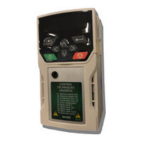
Copeland E3 Quick Start Manual (12 pages)
Setup with M400 VFD Drive
Brand:
Copeland
| Category:
Controller
| Size: 12 MB
Advertisement
Copeland E3 Reference Card (2 pages)
Supervisory Control
Brand:
Copeland
| Category:
Controller
| Size: 0 MB
Advertisement
Related Products
Copeland EazyCool EC2-5X1
Copeland E2
Copeland EXD-SH1
Copeland EXD-SH2
Copeland EAC-SE025AE-TFMR621
Copeland EVH-322011
Copeland EVH-344087
Copeland EVH-344310
Copeland EVH-344012
Copeland EVH-355080
Copeland Categories
Controller
Air Compressor
Measuring Instruments
Thermostat
Control Unit
More Copeland Manuals
Login
Sign In
OR
Sign in with Facebook
Sign in with Google
Upload manual
Upload from disk
Upload from URL