Sign In
Upload
Manuals
Brands
Conviron Manuals
Climate chamber
GEN2000
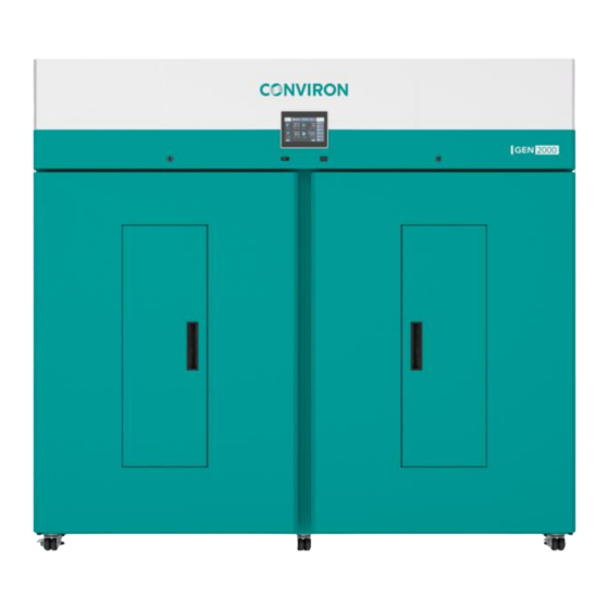
Conviron GEN2000 Manuals
Manuals and User Guides for Conviron GEN2000. We have
2
Conviron GEN2000 manuals available for free PDF download: Operator's Manual
Conviron GEN2000 Operator's Manual (65 pages)
Brand:
Conviron
| Category:
Climate chamber
| Size: 4 MB
Table of Contents
Preface
3
Rohs Compliance
4
Document Conventions
4
Service and Technical Support
5
Table of Contents
6
Precautions
12
Hazard Identification Symbols
12
Table 1-1 Hazard Identification Symbols
12
General Precautions
13
Chamber Features
15
GEN1000 Configurations
15
GEN1000 Germinator (GE)
15
Gen1000-Eco
15
GEN2000 Configurations
15
Plant Placement
15
Control System
16
Central Management System (Optional)
16
CMP-Link (Optional)
16
Convirondirect (Optional)
16
UPS Uninterrupted Power Supply (Optional)
16
Webcard (Optional)
16
Network Connectivity
16
Figure 3-5 GEN1000 Chamber Airflow
16
Levelers
17
Instrument Port
17
Condensate Pump (Optional)
17
Condensate Pan (Optional for GEN2000)
17
Air Intake and Exhaust
17
Hepa Filter (Optional)
17
Ducted Collar (Optional)
17
Temperature and Humidity Sensor
17
Lighting
17
SH-XTIER (Optional)
17
High Light Intensity (Optional)
18
Light Sensor (Optional)
18
PFR-LED (Optional)
18
Low Temperature (Optional)
18
Water Cooled Condensing Unit (Optional)
18
Humidity Control
18
Bypass Dehumidification - BDH (Optional)
18
Dehumidification by Desiccant Dryer - DEH (Optional)
19
Ultrasonic Humidification - USH (Optional for GEN2000)
19
Compact Pump Spray Nozzle Humidifier - CPSNH (Optional for GEN2000)
19
Carbon Dioxide Additive Control
19
CO2 Additive (Optional)
19
CO2 Monitoring (Optional)
19
CO2 Scrubber (Optional for GEN1000)
19
Central Alarm Contact
19
To Install the CAC
19
Installation
20
Chamber Temperature Range
20
Gen1000
20
Gen2000
20
Chamber Clearance
20
Power Supply
20
Water Supply
20
Condensate Drain
21
Removing the Chamber from the Shipping Pallet
21
To Remove the Chamber from the Pallet with a Forklift
21
Figure 3-2 Position the Forks
21
Table 3-1 Water Supply Parameters
21
To Remove the Chamber from the Pallet Using the Optional Ramp
22
Figure 3-3 Remove the Chamber from the Pallet Using the Optional Ramp
22
Moving the Chamber into Final Position
23
To Move the Chamber into Position
23
Leveling the Chamber
23
To Adjust the Levelers
23
Figure 3-4 Chamber Levelers
23
Configuration Kit Overview
24
Airflow
24
SH Configuration
25
Figure 3-6 GEN2000 Chamber Airflow
25
Figure 3-7 SH Configuration
25
IN Configuration
26
Figure 3-8 SH X-TIER Configuration
26
Figure 3-9 in Configuration
26
TA Configuration
27
Unifloor
27
Removing the Unifloor
27
Figure 3-10 TA Configuration
27
Figure 3-11 Unifloor
27
Replacing the TA Back-Wall Plenum
28
Remove All Canopies & Shelves Figure 3-13 Remove All Plenum Screws
28
Figure 3-14 Remove the Plenum
28
TC Configuration
29
To Install the TC Kit
29
Figure 3-15 TC Configuration
29
Removing an Air Shelf
31
Removing an Air Shelf Bracket
31
Figure 3-16 TC Kit Installation
31
Gen1000-Ge
32
Gen1000-Eco
32
Figure 3-17 GE Configuration
32
Figure 3-18 ECO SH Configuration
32
Installing the Light Canopies and Shelving Configuration Kits
33
Lamp Canopies
33
Light Canopy Control
33
Light Canopy Power
33
To Install Lamp Canopy Supports Brackets
33
Figure 3-19 GEN1000, GEN2000 Shelf Spacing
33
Figure 3-20 Install the Canopy Support Brackets or Adjustable Wire Shelves
33
To Install the Lamp Canopies
34
To Remove the Lamp Canopies and Shelves
34
Wire Shelves
34
Figure 3-21 Install the Canopies
34
Figure 3-22 Control Connection
34
Figure 3-23 Power Connection
34
To Install the Wire Shelves
35
Figure 3-24 Install the Shelf Clips
35
Figure 3-25 Wire Shelf Supports
35
Adjustable Wire Shelves (GEN1000-GE)
36
Installing Adjustable Wire Shelves
36
To Install Adjustable Wire Shelves
36
Figure 3-26 Wire Shelves, Support Brackets, and Seedling Tray
36
Figure 3-27 Shelf Installed Onto Support Bracket
36
To Install the Optional Seedling Tray
37
GEN1000-GE Adjustable Shelf Spacing
37
Figure 3-28 Seedling Tray
37
External Connections
38
Figure 3-29 Back Panel Connections
38
Table 3-2 Back Panel Connection Descriptions
38
GEN1000 Connecting the Electrical Cord
39
GEN2000 Connecting the Chamber to the Electrical Mains
39
To Connect Chamber to the Electrical Mains
39
Figure 3-30 Mains Connection Blocks
39
Start up
41
Start up Procedure
41
Figure 4-1 Nitrogen Warning Label
41
Visual Checks
42
Operation
43
Control and Monitoring
43
LED and Fluorescent Lighting
43
Lighting and Options
44
LED Lighting
44
Fluorescent Lighting TC Option
44
Closed Loop Dimmable Lighting System
44
Germination Material Placement
44
Aspirator
45
Instrumentation Port
45
Figure 5-1 Aspirator
45
Figure 5-2 Instrumentation Port Location
45
Fresh Air Inlet and Exhaust Ports
46
Fan Speed Control
46
To Adjust the Fan Speed
46
Figure 5-3 Fresh Air Inlet and Exhaust Port Location
46
Additive Carbon Dioxide Control - CO2 (Optional)
47
Adjusting the CO2 Control
48
To Adjust the CO2 Control
48
Central Management System - CMS Option
48
Shutdown
48
Cleaning and Maintenance
49
Disconnecting the Mains Power
50
Gen1000
50
Gen2000
50
Disconnecting the Optional UPS Backup Power
50
Cleaning the Chamber
51
Replacing LED or Fluorescent Lamps
51
To Replace an LED Tube
51
To Replace a Fluorescent Tube
52
Performing Maintenance Inside the Machine Compartment
52
To Remove the Machine Compartment Access Panel
52
Figure 6-1 LED Tube Orientation
52
Maintaining the Ultrasonic Humidity System (USH)
53
Gen2000
53
Remove the Screws from the Top Cover Figure 6-3 Machine Compartment Access Panel Screws
53
To Remove and Clean the USH Box
54
Figure 6-4 Remove the USH Box from the Chamber
54
Figure 6-5 Remove the USH Box Lid
54
To Replace the Ceramic Discs
55
Calibrating the Temperature and Humidity Sensor
55
Figure 6-6 Ceramic Disc Replacement
55
Adjusting the Door
56
Cleaning the Condensate Pump and Condensate Pan
56
To Clean the Condensate Pump and Pan
56
Figure 6-7 Condensate Pump Connection
56
GEN2000 Cleaning the Condensate Pump and Condensate Pan in TA Configuration
57
Cleaning the Fresh Air Inlet Filter
57
Troubleshooting
58
Troubleshooting the Chamber
58
Chamber Won't Start
58
Chamber Won't Cool
58
Chamber Won't Heat
58
Chamber Won't Make Humidity
58
Chamber Lamp Won't Light up after Replacement
58
Optional UPS Doesn't Work
59
GEN1000 Fuse Schedule
59
GEN2000 Fuse Schedule
59
Technical Specifications
60
Gen1000
60
Gen2000
61
Exterior Dimensions
61
Interior Dimensions
61
Environmental Requirements
61
Figure 8-1 Sample GEN1000 Rating Plates
62
Figure 8-2 Sample GEN1000-GE Rating Plate
62
Figure 8-3 Sample GEN2000 Rating Plates
62
Additional Information
63
Terms & Definitions
63
Table 9-1 Terms and Definitions
63
Product Updates
64
Advertisement
Conviron GEN2000 Operator's Manual (66 pages)
Brand:
Conviron
| Category:
Climate chamber
| Size: 2 MB
Table of Contents
Table of Contents
6
1 Precautions
11
Hazard Identification Symbols
11
Table 1-1 Hazard Identification Symbols
11
General Precautions
12
2 Chamber Features
15
Chamber Configurations
15
Control System
15
Ventilation
15
Instrumentation Ports
15
Levelers
16
Central Alarm Contact
16
Central Management System (Optional)
16
CMP-Link (Optional)
16
Hardware Options
17
3 Installation
19
Chamber Temperature Range
19
Chamber Clearance
19
Power Supply
19
Water Supply
20
Condensate Drain
20
Removing the Chamber from the Shipping Pallet
20
Table 3-1 Water Supply Parameters
20
Figure 3-1 Metal Shipping Bracket
21
Figure 3-2 Fork Placement
21
Moving the Chamber into Final Position
22
Levelling the Chamber
22
Figure 3-3 Chamber Levelers
22
Configuration Kit Overview
23
Airflow
23
Figure 3-4 Chamber Airflow
23
SH Configuration
24
Figure 3-5 SH Configuration
24
Figure 3-6 X-TIER Option for the SH Configuration
24
TA Configuration
25
Unifloor
25
Figure 3-7 TA Configuration
25
Figure 3-8 Unifloor
25
TC Configuration
26
IN Configuration
26
Figure 3-9 TC Configuration
26
Figure 3-10 in Configuration
26
Lamp Canopies and Wire Shelves
27
Figure 3-11 Canopy Supports and Connections
27
Figure 3-12 Wire Shelf Supports
27
Installing the Lamp Canopies and Wire Shelves
28
Installing Lamp Canopies
28
Figure 3-13 GEN2000 Shelf Spacing
28
Figure 3-14 Install the Canopy Support Brackets
29
Figure 3-15 Install the Canopies
29
Figure 3-16 Control Connection
29
Figure 3-17 Power Connection
29
Installing Wire Shelves
30
Figure 3-18 Install the Shelf Clips
30
Figure 3-19 Shelf Installed Onto Clip
30
Removing the Lamp Canopies, Shelves, and the Unifloor
31
Removing a Lamp Canopy and Lamp Canopy Supports
31
Removing a Wire Shelf and Wire Shelf Clip
31
Removing an Air Shelf
31
Removing an Air Shelf Bracket
31
Removing the Unifloor
31
Replacing the Back-Wall Plenum
32
Figure 3-20 Remove All Canopies & Shelves
32
Figure 3-21 Remove All Plenum Screws
32
Figure 3-22 Remove the Plenum
33
Figure 3-23 Replacement Plenum Installation Order
33
Connecting the Communication, Central Alarm Contact , and Condensate Pump
35
Connecting the Chamber to the Electrical Mains
35
Figure 3-24 Back Panel Connections
35
Table 3-2 Back Panel Connection Descriptions
35
4 Start up
37
Start up Procedure
37
Visual Checks
38
5 Operation
39
Control and Monitoring
39
Fluorescent and LED Lighting
39
Lighting Options
40
LED Lighting
40
Fluorescent Lighting - Optional
40
Open and Closed Loop Dimmable Lighting System
40
Aspirator
41
Instrumentation Port
41
Figure 5-1 Aspirator
41
Figure 5-2 Instrumentation Port Location
41
Fresh Air Inlet and Exhaust Ports
42
Fan Speed Control
42
Plant Placement
42
Figure 5-3 Fresh Air Inlet and Exhaust Port Location
42
Bypass Dehumidification - BDH Option
43
Additive Carbon Dioxide Control - CO Option
43
Setting up the Additive CO Control
43
Adjusting the CO Control
44
Central Management System - CMS Option
44
Figure 5-4 Optional CO Connection Location
44
Shutdown
45
6 Cleaning and Maintenance
47
Disconnecting the Mains Power
48
Disconnecting the Optional UPS Backup Power
48
Figure 6-1 Disconnecting UPS Battery Backup Power
48
Cleaning the Chamber
49
Replacing Lamps
49
Calibrating the Temperature and Humidity Sensor
50
Figure 6-2 LED Tube Orientation
50
Maintaining the Ultrasonic Humidity System (USH)
51
Figure 6-3 GEN2000 USH Tank Access Panels
51
Figure 6-4 Remove the USH Box from the Chamber Sequence
52
Figure 6-5 USH Interior Details
52
Calibrating the Temperature and Humidity Sensor
53
Figure 6-6 Ceramic Disc Replacement
53
Adjusting the Door
54
Cleaning the Condensate Pump and Condensate Pan
54
Cleaning the Condensate Pump and Condensate Pan in TA Configuration
54
Figure 6-7 Removeable Floor Plate
54
Cleaning the Fresh Air Filter
55
Performing Maintenance Inside the Machine Compartment
55
Figure 6-8 Machine Compartment Access Panel Screws
55
7 Troubleshooting
57
Troubleshooting the Chamber
57
Figure 7-1 UPS Controller Location
58
Figure 7-2 BATT.FAIL Indicator
58
Fuse Schedule
59
8 Technical Specifications
61
Figure 8-1 Sample GEN2000 Rating Plates
62
9 Additional Information
63
Terms & Definitions
63
Table 9-1 Terms and Definitions
63
Product Updates
64
Advertisement
Related Products
Conviron GEN1000
Conviron GEN1000-ECO
Conviron GEN1000-GE
Conviron PGW40
Conviron Categories
Climate chamber
Controller
Control Systems
Laboratory Equipment
Greenhouse Kit
More Conviron Manuals
Login
Sign In
OR
Sign in with Facebook
Sign in with Google
Upload manual
Upload from disk
Upload from URL