Sign In
Upload
Manuals
Brands
Continental Refrigerator Manuals
Engine
IO-240-B
Continental Refrigerator IO-240-B Manuals
Manuals and User Guides for Continental Refrigerator IO-240-B. We have
1
Continental Refrigerator IO-240-B manual available for free PDF download: Installation And Operation Manual
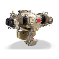
Continental Refrigerator IO-240-B Installation And Operation Manual (146 pages)
AIRCRAFT ENGINE
Brand:
Continental Refrigerator
| Category:
Engine
| Size: 3 MB
Table of Contents
Table of Contents
9
Chapter 1. Introduction
15
Scope and Purpose of this Manual
15
1-1.1. Effectivity Symbols
15
1-1.2. Advisories
15
1-1.3. Using this Manual
15
Figure 1-1. Figure and Index Reference
16
Publications
17
1-2.1. Service Documents
17
1-2.2. Related Publications
18
Table 1-1. Related Publications
18
1-2.3. Publication Access
19
1-2.4. Publication Changes
19
1-2.4.1. Update/Change Distribution
19
1-2.4.2. Suggestions and Corrections
21
Figure 1-3. List of Effective Pages
21
Contact Information
22
Chapter 2. Engine Description
23
General Engine Description
23
2-1.1. Engine Model Number Definition
24
2-1.2. Cylinder Number Designations
24
Figure 2-1. Engine Model Definition
24
Figure 2-2. Cylinder Number Designation
24
Detailed Engine Description
25
2-2.1. Crankcase
25
Figure 2-3. IO-240 Crankcase Features
25
Engine Drive Train
26
2-2.2.1. Crankshaft
26
2-2.2.2. Connecting Rods
27
Figure 2-5. Crankshaft
27
Figure 2-6. Connecting Rod
27
2-2.2.3. Camshaft
28
Figure 2-7. Camshaft
28
2-2.4. Cylinders
29
Figure 2-8. Accessory Case Features
29
Figure 2-9. Cylinder Features
30
2-2.4.1. Pistons
31
2-2.4.2. Hydraulic Valve Tappets
31
Figure 2-10. Piston Features
31
2-2.5. Lubrication System
32
Figure 2-11. IO-240-A Lubrication
32
2-2.5.1. Oil Pump
33
Figure 2-12. IO-240-B Lubrication
33
2-2.5.2. Oil Sump
34
2-2.5.3. Oil Pressure Relief Valve
34
2-2.5.4. Oil Cooler Adapter
34
Figure 2-13. Oil Pump
34
Figure 2-14. IO-240-A Oil Cooler Adapter
35
Figure 2-15. IO-240-B Oil Cooler Adapter
35
Figure 2-16. IO-240-B Oil Cooler/Filter Adapter
35
2-2.6. Ignition System
36
Figure 2-17. Continental Motors Magneto Part Number Structure
36
Figure 2-18. Continental Motors Ignition Distribution
37
Figure 2-19. Slick Ignition Distribution
37
2-2.7. Fuel System
38
2-2.7.1. Fuel Pump
38
Figure 2-20. IO-240 Standard Fuel Injection System
38
Figure 2-21. Standard Fuel Pump
39
Figure 2-22. Altitude Compensating Fuel Pump
39
2-2.7.2. Fuel Injectors
40
2-2.8. Starter Assembly
40
2-2.9. Alternator
40
Figure 2-23. Fuel Injector
40
2-2.10. Engine Cooling
41
Figure 2-24. Engine Cooling
41
2-2.11. Induction System
42
Figure 2-25. IO-240-A Induction System
42
Figure 2-26. IO-240-B Crossflow Induction System
42
Engine Specifications and Operating Limits
43
Table 2-1. IO-240-A Specifications and Operating Limits
43
Table 2-2. IO-240-B Specifications and Operating Limits
45
2-3.1. Accessory Drive Ratios
47
2-3.2. Performance Data
47
Table 2-3. Accessory Drive Ratios
47
2-3.2.1. IO-240-A Performance Charts
48
Figure 2-27. IO-240-A Fuel Flow Vs. Brake Horsepower
48
Figure 2-28. IO-240-A Sea Level Performance
49
2-3.2.2. IO-240-B Performance Charts
50
Figure 2-29. IO-240-B Fuel Flow Vs. Brake Horsepower
50
Figure 2-30. IO-240-B Sea Level Performance
51
Chapter 3.Engine Installation
53
Engine Installation
53
3-1.1. Common Tools and Consumable Supplies Required
53
3-1.2. Engine Receipt and Handling
53
3-1.2.1. Uncrating the Engine
54
3-1.2.2. Crating an Engine for Shipping
54
3-1.2.3. Acceptance Inspection
54
3-1.3. Engine Transport
54
Installation Procedures
56
3-2.1. Prepare the Airframe for Engine Installation
56
3-2.2. Prepare the Engine for Installation
56
3-2.3. Installation Sequence
57
3-2.3.1. Engine Pre-Oiling
59
3-2.3.2. Fuel Purge and Leak Check
60
3-2.4. Installation Inspection
61
3-2.5. Preflight and Run-Up
61
Engine Installation Drawings
63
3-3.1. IO-240-A Installation Drawings
63
Figure 3-1. IO-240-A Top View
63
Figure 3-2. IO-240-A Left Side View
64
Figure 3-3. IO-240-A Front View
65
Figure 3-4. IO-240-A Rear View
66
3-3.2. IO-240-B Installation Drawings
67
Figure 3-5. IO-240-B Top View
67
Figure 3-6. IO-240-B Left Side View
68
Figure 3-7. IO-240-B Front View
69
Figure 3-8. IO-240-B Rear View
70
Figure 3-9. IO-240-B W/Optional Oil Cooler-Filter Adapter Top View
71
Figure 3-10. IO-240-B W/Optional Oil Cooler-Filter Adapter Left Side View
72
Figure 3-11. IO-240-B W/Optional Oil Cooler-Filter Adapter Rear View
73
3-3.3. IO-240 Common Installation Drawings
74
Figure 3-12. Propeller Flange
74
Figure 3-13. Exhaust Flange Dimensions
75
Figure 3-14. Standard Fuel Pump Installation
75
Figure 3-15. Standard Fuel Pump Adjustments
76
Figure 3-16. IO-240-B Altitude Compensating Fuel Pump Adjustments
76
Figure 3-17. Throttle Lever Installation
77
Figure 3-18. Oil Cooler Adapter Connections
77
Figure 3-19. Oil Cooler Adapter Connections
78
Figure 3-20. Oil Cooler-Filter Adapter Connections
78
Figure 3-21. IO-240-A Air Intake Flange
79
Figure 3-22. Alternator Connections
79
Figure 3-23. Engine Mounts
80
Figure 3-24. Continental Motors Magneto Ignition Schematic
81
Figure 3-25. Champion (Slick) Magneto Ignition Schematic
81
Figure 3-26. Airframe Ignition Switch Connections to Magneto
82
Chapter 4. Engine Operation
83
Introduction
83
Flight Prerequisites
83
4-2.1. Oil Change Interval
84
4-2.2. Engine Fuel Requirements
84
4-2.3. Flight Check and Break-In
84
4-2.3.1. Engine Break-In
85
Table 4-1. IO-240 Operating Limits
86
4-2.3.2. Flight Check
87
Normal Operation
89
4-3.1. Pre-Operational Requirements
89
4-3.2. Engine Start
90
4-3.2.1. Cold Start
91
4-3.2.2. Flooded Engine
92
4-3.2.3. Hot Start
92
4-3.3. Ground Run-Up
92
4-3.4. Taxi Preparation
94
4-3.5. Power Control
94
4-3.6. Take-Off
95
4-3.7. Climb
96
4-3.8. Cruise
97
4-3.9. Descent
98
4-3.10. Landing
98
4-3.11. Engine Shutdown
99
Emergency Operation
100
4-4.1. Engine Fire During Start
100
4-4.2. Engine Fire During Flight
100
4-4.3. In-Flight Restart
101
4-4.4. Engine Roughness
101
4-4.5. High Cylinder Head Temperature
101
4-4.6. High Oil Temperature
102
4-4.7. Low Oil Pressure
102
Engine Operation in Abnormal Environments
103
4-5.1. Engine Operation in Extreme Cold
103
4-5.1.1. Engine Preheating
104
4-5.2. Engine Operation in Hot Weather
108
4-5.2.1. Cooling an Engine in Hot Weather
108
4-5.2.2. Engine Restart in Hot Weather
109
4-5.2.3. Ground Operation in Hot Weather
109
4-5.2.4. Take-Off and Initial Climb out in Hot Weather
109
4-5.3. Ground Operation at High Density Altitude
110
Troubleshooting
110
Glossary
112
Appendix A. Glossary
115
Appendix B.torque Specifications
115
General Information
115
B-1.1. Torque Tips
115
Cylinder Torque Procedure
116
Torque Wrench and Extension Calculations
117
Figure B-1. Torque Wrench
117
Figure B-2. Drive Extensions
117
Figure B-3. Extension Increases Applied Torque
118
Figure B-4. Extension Decreases Applied Torque
118
Table B-1. General Torque Specification
119
Table B-3. Hose Fitting ("B" Nut) Torque Specification
120
Table B-2. Tube Fitting Torque Specifications
120
Table B-4. Component Specific Torque Specifications
121
Table B-5. Specific Torque for Non-Lubricated Hardware
124
Appendix C.standard Practices
125
Handling Parts
125
Replacement Parts
126
C-2.1. Background
126
C-2.2. Acceptable Replacement Parts
126
C-2.2.1. Know Your Supplier
127
C-2.3. 100% Parts Replacement Requirements
127
C-2.4. Mandatory Overhaul Replacement Parts
128
C-2.5. Authorized Oversize/Undersize Parts
128
Torque
128
Figure C-1. Right-Hand-Thread Safety Wire Installation
129
Safety Wiring Hardware
129
Figure C-2. Safety Wire Patterns for Right-Hand Threads
130
Figure C-3. Tab Washer Installation
131
Tab Washer Installation
131
Helical Coil Insert Replacement
132
C-6.1. Helical Coil Removal
133
Figure C-4. Helical Coil Extraction Tool
133
C-6.2. Helical Coil Insertion
134
Figure C-5. Installing a Helical Coil Insert
134
Stud Replacement
135
C-7.1. Stud Removal
135
C-7.1.1. Size-On-Size Rosan® Stud Removal
135
C-7.1.2. Step-Type Rosan® Stud Removal
136
Figure C-6. Rosan® Stud Removal Tool
136
Figure C-7. Rosan® Stud Removal Tool Installed on Stud
136
C-7.2. Stud Installation
137
Figure C-8. Stud Sizes
137
C-7.2.1. Rosan® Stud Installation
138
Figure C-10. Rosan® Stud Installation Dimensions
138
Figure C-9. Minimum Material Thickness for Helical Coil Insertion
138
Cotter Pin Installation
139
Figure C-11. Cotter Pin Installation
139
Fuel System Service
140
C-9.1. Fuel System Purge
140
C-10. Gasket Maker® Application
141
C-11. Gasket Installation
142
C-12. Hose and Tubing Installation
143
Figure C-12. Installing Hoses and Fittings
143
C-13. Harness Routing
144
Advertisement
Advertisement
Related Products
Continental Refrigerator IO-240-A
Continental Refrigerator IOF-240-B
Continental Refrigerator Permold IOF-550-B
Continental Refrigerator Permold IOF-550-N
Continental Refrigerator Permold IOF-550-C
Continental Refrigerator Permold IOF-550-P
Continental Permold IOF-550-R
Continental Refrigerator iDT
Continental Refrigerator C75
Continental Refrigerator C85
Continental Refrigerator Categories
Refrigerator
Freezer
Indoor Fireplace
Automobile Accessories
Control Unit
More Continental Refrigerator Manuals
Login
Sign In
OR
Sign in with Facebook
Sign in with Google
Upload manual
Upload from disk
Upload from URL