Sign In
Upload
Manuals
Brands
Compu-aire Manuals
Controller
SYSTEM 2200 Plus 3L
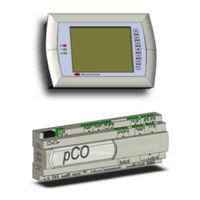
Compu-aire SYSTEM 2200 Plus 3L Controller Manuals
Manuals and User Guides for Compu-aire SYSTEM 2200 Plus 3L Controller. We have
2
Compu-aire SYSTEM 2200 Plus 3L Controller manuals available for free PDF download: User Manual, Quick Reference
Compu-aire SYSTEM 2200 Plus 3L User Manual (82 pages)
Brand:
Compu-aire
| Category:
Controller
| Size: 2 MB
Table of Contents
Table of Contents
2
1 Introduction
8
2 Quick Reference Guide
8
3 Sequence of Operations
9
Standard Units in General
9
How to Turn the Unit on
9
Lead/Lag Redundancy - P-LAN Network
9
Air Cooled DX with Chilled Water Plus
10
Air Side Economizer
11
Water Side Economizer Energy Miser (EM) Unit Using 2-Way Valves
11
Water Cooled Energy Miser
13
Dry Fluid Cooler with Energymizer
14
Special Pump and Dry Fluid Cooler Control Logic
16
Optional Features
16
4 Configuration
17
Main Menu
17
Figure 1- Configurations Screen
17
Screen Settings
18
Figure 2 - Screen Calibration
18
Network Configuration
19
Network Monitor
19
Assigning Private and Shared Terminals
20
Figure 3-Changing Unit ID
20
P-LAN Setup
21
Master Unit (ID=1)
21
Slave Unit (ID=2)
21
P-Lan Wiring
22
General Options
23
5 Technical Specifications
24
Controller and Display
24
General Characteristics
24
Figure 4 - Touch Sensitive Graphical Display
24
Figure 5 - Controller
24
Figure 6 - Internal Built in Display
24
Mechanical Characteristics
25
Electrical Characteristics
26
Digital Inputs
26
Analog Inputs
26
Analog Outputs
27
Digital Outputs
27
P-LAN Network Terminal
27
Cable Length
27
Standard Input / Outputs
28
Optional Features
29
Functional Characteristics
29
Building Management System
29
6 Controller Interface
30
LED Indicators
30
Navigation Buttons
30
7 Navigation Menu
30
Figure 7 - Graphical User Interface
30
Menu Tree
31
Figure 8 - Main Menu
31
Accessing Submenus
32
Main Menu Selection
32
Unit Status
32
Trending
34
Graph Overviews
34
Figure 11- Graphical Sensors Representation
34
Figure 12 - Graph Description
34
Figure 13 - Pressure Graph
34
Icon Description and Function
35
Alarms
37
Alarm Viewing and Function
37
Alarm Reset
37
8 Setup Menu
38
Entering a Password
38
Figure 15-Password Prompt
38
Setup Menu Tree
39
Figure 16 - Entering a Password
39
Figure 17 - Setup Menu
39
Figure 18 - Setup Menu Tree
39
Setpoints
40
Changing Setpoints
40
Figure 19 - Room Temperature Setpoints
40
Figure 20 - Room Humidity Setpoints
40
Changing Alarm Setpoints
41
Clock Setup
41
Time and Date Setup
41
Night Setback
41
Figure 21 - Clock Setup
41
9 Run Time Hour Meters
42
Figure 22 - Component Run Time Meters
42
10 Building Management System (Bms)
43
Modbus
43
Mounting
43
Figure 23 - Building Management System
43
Figure 24 - Communication Protocol
43
Pointlist
46
Lonworks
48
General Characteristics
48
Physical Channels
48
Physical Circuit Board Layout
48
Figure 25 - Lontalk Card
48
LED Color Description
49
Installation
49
Connection to the PCO3 Controller
50
Connection to the Lonworks® Network
50
Service Pin
50
Figure 26 - Remove Plastic Cover
50
Figure 27- Cut out Window
50
Figure 28 - Installing Plugin Card
50
Figure 29 - Replacing Windows Cover
50
WINK Event
51
Bacnet over Tcp/Ip
52
Installation
52
Functions
52
Default Parameters
52
Restarting the Software
53
Configuration
53
Figure 30 - Pcoweb
54
Figure 31 - Window Cover
54
Figure 32 - Installing Pcoweb
54
Figure 33 - Installing Plastic Cover
54
Web Server
55
Accessing the Operating System by Authentication
55
CGI Script
56
Snmp
56
Bacnet
56
Warnings
56
BANET over MS/TP
57
Installation
57
Meaning of the Jumpers
58
Operation
58
Recalling the Factory Configuration ("Factory Bootswitch" Mode)
60
Configuration
60
BACNET Parameter Description
61
11 Technician Menu
62
Alarm Setup
62
Figure 34 - Alarm Configuration
62
Available Alarms
64
Figure 35 - Alarm Delays
64
Figure 36 -Alarm Switch over
64
Digital Input
66
Sensor Offset
66
Network Setup
67
Define a Network
67
Network Assist
67
Figure 37 - Network Setup
67
Figure 38 - Network Assist
67
Manual Control
68
12 Factory Setting
69
Factory Setting Menu Tree
69
Figure 39 - Factory Setting
69
Digital Inputs and Digital Outputs
70
Hvac
72
Analog Inputs and Analog Outputs
75
Changing Passwords
77
Factory Reset
77
13 Troubleshooting Guide
78
Advertisement
Compu-aire SYSTEM 2200 Plus 3L Quick Reference (4 pages)
WITH BUILT IN DISPLAY
Brand:
Compu-aire
| Category:
Controller
| Size: 0 MB
Table of Contents
Controller Layout
1
Navigating
1
Programming Menu
2
Status
3
Alarm
3
Setup
3
Setpoint
4
Advertisement
Related Products
Compu-aire SYSTEM 2500 S
Compu-aire SYSTEM 2500
Compu-aire SYSTEM 2100
Compu-aire Categories
Air Conditioner
Controller
Accessories
More Compu-aire Manuals
Login
Sign In
OR
Sign in with Facebook
Sign in with Google
Upload manual
Upload from disk
Upload from URL