Sign In
Upload
Manuals
Brands
CommScope Manuals
Switch
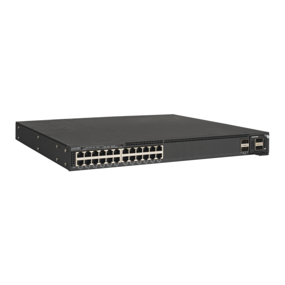
RUCKUS ICX 7550
User Manuals: CommScope RUCKUS ICX 7550 Ethernet Switch
Manuals and User Guides for CommScope RUCKUS ICX 7550 Ethernet Switch. We have
1
CommScope RUCKUS ICX 7550 Ethernet Switch manual available for free PDF download: Hardware Installation Manual
CommScope RUCKUS ICX 7550 Hardware Installation Manual (141 pages)
Brand:
CommScope
| Category:
Switch
| Size: 5 MB
Table of Contents
Table of Contents
3
Preface
7
Document Conventions
7
Notes, Cautions, and Safety Warnings
7
Command Syntax Conventions
7
Document Feedback
8
RUCKUS Product Documentation Resources
8
Online Training Resources
8
Contacting RUCKUS Customer Services and Support
9
What Support Do I Need
9
Open a Case
9
Self-Service Resources
9
About this Document
11
What's New in this Document
11
Supported Hardware and Software
11
Device Overview
13
Hardware Features
13
Port-Side View of the Ruckus ICX 7550 Switch
14
Nonport-Side View of the RUCKUS ICX 7550 Switch
18
Preparing for the Installation
21
Safety Precautions
21
General Precautions
21
ESD Precautions
21
Power Precautions
22
Lifting and Weight-Related Precautions
22
Laser Precautions
23
Facility Requirements
23
Quick Installation Checklists
24
Pre-Installation Tasks
24
Installation and Initial Configuration
25
Shipping Carton Contents
26
Mounting the Device
27
Mounting Options
27
Precautions Specific to Mounting
27
Removing Port Covers
28
Mounting on a Desktop or Flat Surface
28
Two-Post Rack Mount Installation (ICX7000-RMK)
29
Two-Post Rack Mount Installation (ICX-RMK-4POST-TL)
32
Time and Items Required
32
Parts List
32
Flush-Front Mounting
33
Four-Post Rack Mount Installation (ICX-RMK-4POST-TL)
35
Time and Items Required
35
Parts List
35
Flush-Front Mounting
36
Installing the 1U, 1.5U, and 2U Universal Kit for Four-Post Racks (XBR-R000295)
39
Time and Items Required
39
Parts List
40
Flush-Front Mounting the Device in a Rack
41
Flush-Rear (Recessed) Mounting the Device in the Rack
46
Connecting ICX 7550 Devices in a Stack
55
Stacking Configuration Requirements
55
ICX 7550 Stacking Topologies
55
ICX 7550 Two-Unit Stack with Linear-Topology Trunk
56
ICX 7550 Stacking Configuration Notes
57
ICX 7550 Module 2 Stacking and Uplink Options
57
ICX 7550 Module 2 Profile Compatibility with Module 3
58
Initial Setup and Verification
59
Items Required
59
Providing Power to the Device
59
Establishing a First-Time Connection to the Console Port
59
Performing the Factory Reset
62
Recovering from a Lost Password
62
Configuring an IP Address for the Device
62
Customizing the Host Name and Chassis Name
63
Setting the Date and Time
64
Establishing a Connection to the Out-Of-Band Management Port
64
Getting In-Band Access
64
Verifying the Correct Operation
64
Backing up the Running Configuration
65
Installing Transceivers and Cables
67
Time and Items Required
67
Precautions Specific to Transceivers and Cables
68
Managing Cables
68
Installing the Ethernet RJ-45 Cables
69
Cleaning the Fiber-Optic Connectors
70
Installing a New Fiber-Optic Transceiver
70
Cabling a Fiber-Optic Transceiver
72
Replacing a Fiber-Optic Transceiver
72
Long-Reach Multimode Adapter Module
73
LRM Adapter Module Part Numbers
73
LRM Adapter Module Specifications
74
Leds
74
ICX 7550 Platform Support for the LRM Adapter Module
74
Unpacking the LRM Adapter Module
75
Monitoring the Device
77
Interpreting Port-Side Leds
77
Status Mode Selection Button and STATUS Leds
81
System Status (SYS) LED
83
Master/Slave Status (MS) LED
84
Software Update Status (UPDATE) LED
84
Diagnostics Status (DIAG) LED
84
Cloud/On-Premise-Smartzone Management Status LED
84
Power Status (PWR1 and PWR2) Leds
85
Interpreting Nonport-Side Leds
85
Rear Panels
85
LED Patterns
87
Pinging an IP Address
87
Tracing a Route
88
Digital Optical Monitoring
88
Monitoring Power and Cooling
88
Power Supplies
91
Power Supply Overview
91
Precautions Specific to Power Supplies
93
Identifying the Airflow Direction
93
Time and Items Required
94
Replacing a Power Supply
94
Inserting a New AC Power Supply
94
Installing the AC Power Cord Strap
96
Inserting a New DC Power Supply
98
Grounding the RUCKUS ICX 7550 Switch
100
Default and Optional Lugs
100
Connecting to the Grounding Terminal
101
Fan Assemblies
103
Fan Assembly Overview
103
Precautions Specific to Fan Assemblies
104
Identifying the Airflow Direction
104
Time and Items Required
105
Replacing a Fan Assembly
105
Inserting a New Fan Assembly
105
Expansion Modules
109
Expansion Module Overview
109
Precautions Specific to Expansion Modules
110
Time and Items Required
110
Installing or Replacing an Expansion Module
110
Resolving Module 3 Mismatches
112
Resolving Module 3 Mismatches in a Standalone RUCKUS ICX 7550 Switch
112
Resolving Module 3 Mismatches in a RUCKUS ICX 7550 Stack
112
RUCKUS ICX 7550 Switch Technical Specifications
115
System Specifications
115
Ethernet
115
Leds
116
Other
116
Weight and Physical Dimensions
117
Environmental Requirements
117
Power Supply Specifications (Per PSU)
118
Power Consumption (Typical Configuration)
118
Power Consumption (Maximum Configuration)
119
Power Consumption (Modules)
120
Data Port Specifications (Ethernet)
120
Serial Port Specifications (Pinout - USB Type-C)
121
Serial Port Specifications (Pinout RJ-45)
122
Serial Port Specifications (Protocol)
122
Memory Specifications
123
Regulatory Compliance (EMC)
123
Regulatory Compliance (Safety)
123
Regulatory Compliance (Environmental)
123
Regulatory Statements
125
FCC Warning (US Only)
125
Canadian Requirements
125
Europe and Australia (CISPR 32 Class a Warning)
125
Germany
125
VCCI Statement
126
KCC Statement (Republic of Korea)
126
China CCC Statement
127
BSMI Statement (Taiwan)
127
Cautions and Danger Notices
129
Cautions
129
General Cautions
129
Electrical Cautions
133
Danger Notices
135
General Dangers
135
Electrical Dangers
136
Dangers Related to Equipment Weight
139
Laser Dangers
140
Advertisement
Advertisement
Related Products
CommScope RUCKUS ICX 7450
CommScope ICX7400-4X1GF
CommScope ICX7400-4X10GF
CommScope ICX7400-4X10GC
CommScope ICX7400-1X40GQ
CommScope Ruckus ICX 7750
CommScope ION-M85P
CommScope ION-M80
CommScope ION-85HP EU
CommScope iP-600B-12-SC-MMF
CommScope Categories
Network Hardware
Antenna
Cables and connectors
Wireless Access Point
Enclosure
More CommScope Manuals
Login
Sign In
OR
Sign in with Facebook
Sign in with Google
Upload manual
Upload from disk
Upload from URL