Sign In
Upload
Manuals
Brands
CommScope Manuals
Network Hardware
ION-M23 SDARS
CommScope ION-M23 SDARS Manuals
Manuals and User Guides for CommScope ION-M23 SDARS. We have
1
CommScope ION-M23 SDARS manual available for free PDF download: Manual
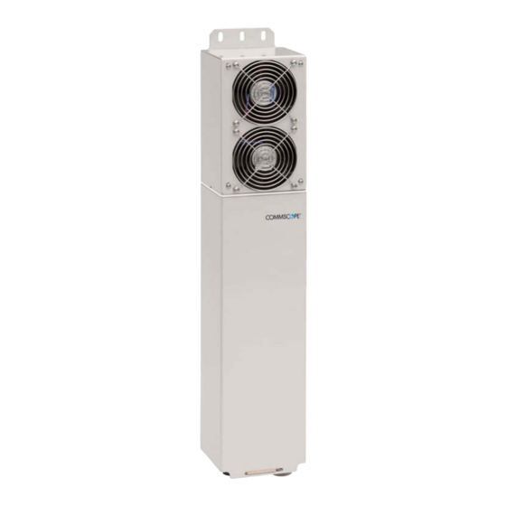
CommScope ION-M23 SDARS Manual (47 pages)
Optical Remote Unit, M-Cabinet, 3-Sector
Brand:
CommScope
| Category:
Network Hardware
| Size: 1 MB
Table of Contents
Table of Contents
3
1 General
5
Used Abbreviations
5
Health and Safety
6
Property Damage Warnings
6
Compliance
7
About Commscope
10
International Contact Addresses for Customer Support
11
2 Introduction
13
Purpose
13
The Ion-M23 Sdars 3-Sector
13
3 Functional Description
15
General
15
Accessory Equipment
15
Fan-Protection Kit
15
Accessories
15
7. Appendix
15
Figure 3-1 Block Diagram ION-M23 SDARS
15
Figure 3-2 System Overview with an ION-M23 SDARS Remote Unit
15
4 Commissioning
16
Mechanical Installation
16
Health and Safety for Mechanical Installation
16
Property Damage Warnings for Mechanical Installation
16
Wall-Mounting Procedure
18
Figure 4-1 Wall Mounting, (Metric Dimensions)
18
Pole Mounting
19
Figure 4-2 Pole-Mounting Kit
19
Figure 4-3 Pole Mounting (Metric Dimensions)
20
Mounting of Fan Protection
21
Figure 4-4 Mounting Procedure for Fan Protection, (Metric Dimensions)
21
Electrical Installation
22
Health and Safety for Electrical Installation
22
Property Damage Warnings for Electrical Installation
22
Connections
23
Grounding (Earthing)
23
Figure 4-5 Connector Flange of ION-M23 SDARS
23
Figure 4-6 Grounding Bolt (Left) and Schematic View (Right)
23
Connection of the Antenna Cables
24
Cleaning Procedure for RF Cable Connectors
25
Antenna Cable Connector Assembly
28
Optical-Fiber-Cable Connection - Rules
29
Protective Plug
31
Figure 4-7 Protective-Plug Assembly
31
Protective-Tube Kit
33
Figure 4-8 Tube-Kit Installation
33
External-Alarm Inputs and Outputs
34
Figure 4-9 Flange Connector, 5 Poles
34
Figure 4-10 Alarm Inputs (Optocoupler)
34
Figure 4-11 Alarm Outputs (Optocoupler)
35
Figure 4-12 Flange Connector, 7 Poles
35
Power Connection
36
Figure 4-13 Power Supply Cables (AC)
36
Figure 4-14 Power Supply Cable (DC)
36
Commisioning Flowchart
37
5 Alarms and Troubleshooting
39
Figure 7-1 Cabinet Drawing
43
Advertisement
Advertisement
Related Products
CommScope ION-M17EHP/19P
CommScope ION-7P
CommScope ION-85P
CommScope ION-M7P
CommScope ION-M17P
CommScope ION-M85P
CommScope ION-M19P
CommScope ION-M7P/17EHP
CommScope ION-M8P S
CommScope ION-M80
CommScope Categories
Network Hardware
Antenna
Cables and connectors
Wireless Access Point
Enclosure
More CommScope Manuals
Login
Sign In
OR
Sign in with Facebook
Sign in with Google
Upload manual
Upload from disk
Upload from URL