Sign In
Upload
Manuals
Brands
COBHAM Manuals
Transceiver
SAILOR 7222 VHF DSC
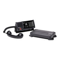
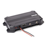
COBHAM SAILOR 7222 VHF DSC Device Manuals
Manuals and User Guides for COBHAM SAILOR 7222 VHF DSC Device. We have
3
COBHAM SAILOR 7222 VHF DSC Device manuals available for free PDF download: Installation Manual, User Manual, Quick Start Manual
COBHAM SAILOR 7222 VHF DSC Installation Manual (110 pages)
Brand:
COBHAM
| Category:
Receiver
| Size: 5 MB
Table of Contents
Table of Contents
4
Chapter 1 Introduction
10
VHF Radio with DSC Class a
10
Figure 1-1: Controls on the Front Plate of the Control Unit
11
Chapter 1 Introduction
11
Accessories Available
12
Table 1-1: Accessories
12
System Configuration - Example
14
Figure 1-2: System Configuration, Example
14
Chapter 2 Installation
15
Unpacking and Initial Inspection
15
Installing the VHF Radio
16
Figure 2-2: Control Unit, Overhead Mounting
18
Figure 2-3: Control Unit, Mounting with the Mounting Bracket
19
Figure 2-4: Control Unit, Drilling Plan for the Mounting Bracket
19
Figure 2-5: SAILOR 7224 Control Unit Dimensions for Flush Mount
20
Figure 2-6: Control Unit, Cutout for Flush Mount
20
Figure 2-7: Control Unit, Flush Mount
21
Figure 2-8: Transceiver Unit, Dimensions
22
Figure 2-9: SAILOR 6201 Handset with Cradle, Dimensions for Mounting
23
Connectors on the SAILOR 7224 Control Unit
24
Figure 2-10: SAILOR 7224 Control Unit, Rear Panel Connectors
24
Table 2-2: Pin Allocation, ACC Connector
25
Table 2-3: Pin Allocation, AUX Connector
26
Table 2-4: Pin Allocation, OPT Connector
27
Table 2-5: Pin Allocation, CTRL Connector
28
Table 2-7: Pin Allocation, USB Connector
30
Table 2-8: Pin Allocation, Power
31
Connectors on SAILOR 7226 VHF Transceiver Unit
32
Figure 2-11: SAILOR 7226 VHF Transceiver Unit, Connectors
32
Figure 2-12: Transceiver Unit, Remove Cover
33
Figure 2-13: Transceiver Unit, Connect Power Cables
33
VHF and DSC Antenna Installation
35
Wiring of Connection Boxes
37
Figure 2-16: SAILOR 6207 Connection Box for Parallel Handsets, Mounting
37
Figure 2-17: SAILOR 6207 Connection Box for Parallel Handsets, Wiring
37
Figure 2-18: SAILOR 6207 Connection Box for Parallel Handsets, Diagram
38
Figure 2-19: SAILOR 6208 Control Unit Connection Box, Mounting
39
Figure 2-20: SAILOR 6208 Control Unit Connection Box for Parallel Handsets, Wiring
39
Figure 2-21: SAILOR 6208 Control Unit Connection Box, Diagram
40
Figure 2-22: SAILOR 6209 Accessory Connection Box, Mounting
41
Figure 2-23: SAILOR 6209 Accessory Connection Box, Wiring
41
Connect the Control Unit to the Transceiver Unit
42
Figure 2-24: SAILOR 6209 Accessory Connection Box, Diagram
42
Chapter 3 First-Time Power up
43
General Use and Navigation
43
Entering the MMSI Number
44
Forced Low Power AUX Input Control
45
Chapter 4 Configuration
46
Administrator Access
46
Settings
47
Figure 4-1: SETTINGS Menu Tree
48
Table 4-1: SETTINGS > RADIO Menu
49
Table 4-2: SETTINGS > CONTROLLER Menu
50
Table 4-3: SETTINGS > CHANNELS Menu
50
Table 4-4: SETTINGS > CHANNELS, Channel Properties
51
Table 4-5: Explanation of Channel Properties
52
Table 4-6: SETTINGS > DSC Menu
53
Table 4-7: SETTINGS > POWER SUPPLY Menu
55
Table 4-8: SETTINGS > NMEA Menu
55
Table 4-9: SETTINGS > NETWORK Menu
56
Table 4-10: SETTINGS > SYSTEM Menu
57
Table 4-11: SETTINGS > REMOTE CONTROL
58
Table 4-12: SETTINGS > about
59
Chapter 5 Service & Maintenance
60
Contact for Support
60
Software Update
60
Alerts in the Bridge Alert Management System (BAM)
63
DSC Self Test
63
Maintenance
64
Figure 5-1: Fuse in Transceiver Unit
64
Returning Units for Repair
65
SAILOR 7226 VHF Transceiver Unit
66
Table A-1: Transceiver Unit, General Specifications
66
Table A-2: Transceiver Unit, Detailed Specifications
66
SAILOR 7224 Control Unit
68
Table A-3: Control Unit Specifications
68
General DSC Specifications
69
NMEA Specifications
69
Table A-4: General DSC Specifications
69
Table A-5: NMEA Specifications
69
Figure A-1: NMEA Interface Description
70
Table A-6: List of Alerts
71
Appendix B NMEA Sentences
72
NMEA Sentences Used
72
Table B-1: Multicast Addresses and Ports for LWE Transmission Groups
72
Table B-2: Supported Sentences
73
Table B-3: Other Network Functionality, Input
74
Table B-4: Other Network Functionality, Output
74
Sentence Use Reference
75
Table B-5: ACN - Alert Command (Input
75
Table B-6: ALC - Cyclic Alert List (Output
76
Table B-7: ALF - Alert Sentence (Output
76
Table B-8: ARC Sentence - Alert Command Refused
77
Table B-9: GGA Sentence - Global Positioning System (GPS) Fix Data
77
Table B-10: GLL Sentence - Geographic Position (Output
78
Table B-11: GNS Sentence - Fix Data (Input
78
Table B-12: HBT Sentence - Heartbeat Supervision Sentence (Input
79
Table B-13: RMC Sentence - Recommended Minimum Specific GNSS Data (Input
79
Table B-14: ZDA Sentence - Time and Date (Output
80
Appendix C System Configurations
81
System Configuration Examples
81
Figure C-1: System Configuration, SAILOR N163S Power Supply
82
Figure C-2: System Configuration, SAILOR 6201, GNSS, Ext. Loudspeaker and Alarms
83
Figure C-3: System Configuration, GNSS and SAILOR 6270 External Loudspeaker
84
Figure C-4: System Configurations, 2 SAILOR 6201 Handsets and a GNSS
85
Figure C-7: System Configuration, CAN Bus, SAILOR 6204 CSM, Far from the VHF Radio
88
Figure C-8: System Configuration: CAN Bus, 2 SAILOR 6204 Csms, Far from VHF Radio
89
Figure C-9: System Configuration: CAN Bus, 2 SAILOR 6204 Csms, Close VHF, Small
90
Figure C-10: System Configuration: CAN Bus, 2 SAILOR 6204 Csms, in Bridge Wings
91
Figure C-11: System Configuration: CAN Bus, 3 SAILOR 6204 Csms
92
Figure C-12: System Configuration: CAN Bus, 4 SAILOR 6204 Csms
93
Figure C-13: System Configuration: Installation of LAN
94
Figure C-14: System Configuration: Installation of Central Alert Management (CAM)
95
Figure C-15: System Configuration: Installation of a Printer
96
Cable Requirements
97
Table C-1: Cable Overview
97
Table C-2: Cable Specifications for Cable 2
98
Table C-3: Pin Allocation, Power to Control Unit
99
Table C-4: Cable Specifications for Cable 5
99
Table C-5: Cable Specifications for Cable 8 (AUX
100
Table C-6: Cable Specifications for Cable 8 (CTRL
102
Table C-7: Pin Allocation, LAN Connector
103
Glossary
105
Index
107
Advertisement
COBHAM SAILOR 7222 VHF DSC User Manual (95 pages)
Brand:
COBHAM
| Category:
Transceiver
| Size: 3 MB
Table of Contents
Ground the Equipment
6
Installation and Service
6
RF Exposure Hazards and Instructions
6
Safety Warning
6
Cyber Security
9
Installation Guidance
9
User Guidance
9
Radio for Occupational Use
10
Training Information
10
Installation Considerations, Radiation
11
Warning, Radiation
11
Manual Overview
12
Related Documents
12
Table of Contents
13
Chapter 1 Introduction
15
VHF Radio with DSC Class a
15
Controls on the Front Plate of the Control Unit
16
SAILOR 7222 VHF DSC Display
17
Accessories Available
18
System Configuration - Example
21
Chapter 2 Operation
23
General Use and Navigation
24
Power On, Volume and Squelch
24
DSC and MMSI Number
25
Speaker Devices
25
Working Channel and Dimming the Display
25
Enter Position Manually (no GNSS)
26
Position and MMSI Number
26
Change Channel
27
Idle Screen (Home)
27
Menu Functions in Display
28
Adjusting the Squelch Level
29
Changing the Display Light, Night View
29
Use with a SAILOR 6204 Control Speaker Microphone
30
Basic VHF Operation
31
Quick Guide to Radio Telephone Calls
31
Receiving a Radio Telephone Call on Channel 16
31
VHF Radio Communication
31
Making a Radio Telephone Call on Channel 16
32
VHF Channels
32
Channel Information Always Available in the Display
33
Engagement Status
33
Reduced Transmission Power
34
Watch
34
Scan
35
To Remove a Channel from the Scanning Sequence
35
To Tag a Channel for Scanning
35
Display for Active DSC Session
36
DSC Calls
36
View and Manage DSC Calls
36
What Is a DSC Session
36
Session Line
37
Session Category Icons
38
Session Status
38
On-Screen Keys to Control DSC Sessions
39
Access All DSC Sessions
41
Send, Acknowledge and Cancel Own Distress
42
To Send a Distress Message
42
ALERT: to Send a Distress Message with Specified Nature
43
Power Failure While in Distress
44
To Cancel Own Distress
44
To Receive Acknowledgment of Own Distress
44
Sending a Distress from the SAILOR 6103 Multi Alarm Panel
45
DROBOSE — Distress Relay on Behalf of Someone else
46
Distress Call Log
47
Distress Call with Errors
47
Receiving Distress Calls
47
Receiving Distress Calls from man over Board Devices
47
Tap DSC and Select the Relevant
48
DSC Calls for Communication
49
DSC Call Logs
50
Receiving DSC Calls
50
Replay Function
51
Replaying Recorded Messages
51
Accessing a Settings Page
52
Settings
52
SETTINGS Menu Overview
53
ATIS Code
54
Priority Scan
54
Radio
54
Scan Hang Time
54
Controller
55
Csm Can Termination
55
Ext. Speaker Volume
55
Handset Volume
55
Channels
56
Dsc
58
Auto-Ack
59
Power Supply
60
Network
62
Factory Reset
63
Pairing
63
Printer
64
Reboot
64
Theme
64
About
65
Remote Control
65
To Connect to the Control Unit after Activating
65
Chapter 3 Service & Maintenance
67
Contact for Support
67
DSC Self Test
67
Preventive Maintenance
67
Service & Maintenance
67
Disposal
68
Information of Alerts
69
List of Alert Icons
69
Status Signaling
69
List of Alerts
70
Replacing the Fuse in the Transceiver Unit
71
Warranty and Returning Units for Repair
72
Appendix A Specifications
73
SAILOR 7226 VHF Transceiver Unit
73
SAILOR 7224 Control Unit
75
General DSC Specifications
77
Appendix B Maritime Channels
79
International Channels (INT)
79
US Channels (US)
80
Canadian Channels (CA)
81
Binnenwasser Channels (BI)
82
Alternative Channels (ALT)
83
Private Channels (P)
83
Glossary
85
Index
89
COBHAM SAILOR 7222 VHF DSC Quick Start Manual (3 pages)
Brand:
COBHAM
| Category:
Radio
| Size: 0 MB
Table of Contents
Technical Notification
1
Subject: New Software Release Version 1.06 Including Update Guide
1
Software Update Guide for SAILOR 7222 VHF DSC Class a
2
Important Note
2
Manual Update
3
Advertisement
Advertisement
Related Products
COBHAM SAILOR 7226 VHF
COBHAM SAILOR 7224
COBHAM explorer 727
COBHAM EXPLORER 727 BGAN
COBHAM Explorer 710
COBHAM EXPLORER 7100GX
COBHAM AVIATOR 700D
COBHAM DIGImini 700/1800
COBHAM 7509C
COBHAM 7509D
COBHAM Categories
Antenna
Marine Equipment
Radio
Touch terminals
Receiver
More COBHAM Manuals
Login
Sign In
OR
Sign in with Facebook
Sign in with Google
Upload manual
Upload from disk
Upload from URL