Sign In
Upload
Manuals
Brands
Cinterion Manuals
Control Unit
BGS3
User Manuals: Cinterion BGS3 Quadband GSM GPRS
Manuals and User Guides for Cinterion BGS3 Quadband GSM GPRS. We have
1
Cinterion BGS3 Quadband GSM GPRS manual available for free PDF download: Hardware Interface Description
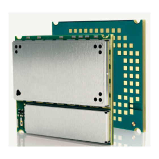
Cinterion BGS3 Hardware Interface Description (109 pages)
Brand:
Cinterion
| Category:
Control Unit
| Size: 1 MB
Table of Contents
Table of Contents
3
Document History
8
1 Introduction
10
Related Documents
10
Terms and Abbreviations
10
Regulatory and Type Approval Information
14
Directives and Standards
14
Table 1: Directives
14
Table 2: Standards of North American Type Approval
14
Table 3: Standards of European Type Approval
14
Table 4: Requirements of Quality
15
Table 5: Standards of the Ministry of Information Industry of the
15
SAR Requirements Specific to Portable Mobiles
16
Table 6: Toxic or Hazardous Substances or Elements with Defined Concentration Limits
16
Safety Precautions
17
2 Product Concept
18
Key Features at a Glance
18
BGS3 System Overview
20
Figure 1: BGS3 System Overview
20
Circuit Concept
21
Figure 2: BGS3 Block Diagram
21
3 Application Interface
22
Operating Modes
23
Table 7: Overview of Operating Modes
23
Power Supply
24
Minimizing Power Losses
24
Figure 3: Power Supply Limits During Transmit Burst
24
Measuring the Supply Voltage VBATT
25
Monitoring Power Supply by at Command
25
Figure 4: Position of Reference Points Batt+And GND
25
Power up / Power down Scenarios
26
Turn on BGS3
26
Turn on BGS3 Using Ignition Line IGT
26
Figure 5: Powerup with Operating Voltage at BATT+ Applied before Activating IGT
27
Figure 6: Powerup with IGT Held Low before Switching on Operating Voltage at BATT
28
Configuring the IGT Line for Use as ON/OFF Switch
29
Turn on BGS3 Using the VCHARGE Signal
29
Figure 7: Timing of IGT if Used as ON/OFF Switch
29
Reset BGS3 Via AT+CFUN Command
30
Reset or Turn off BGS3 in Case of Emergency
30
Using EMERG_OFF Signal to Reset Application(S) or External Device(S)
30
Signal States after Startup
31
Table 8: Signal States
31
Turn off BGS3
32
Turn off BGS3 Using at Command
32
Automatic Shutdown
33
Figure 8: Signal States During Turn-Off Procedure
33
Table 9: Temperature Dependent Behavior
34
Thermal Shutdown
34
Deferred Shutdown at Extreme Temperature Conditions
35
Undervoltage Shutdown
35
Overvoltage Shutdown
36
Automatic GPRS Multislot Class Change
37
Charging Control
38
Hardware Requirements
38
Software Requirements
38
Battery Pack Requirements
39
Figure 9: Battery Pack Circuit Diagram
39
Batteries Tested for Use with BGS3
40
Table 10: Specifications of Battery Packs Suited for Use with BGS3
40
Charger Requirements
41
Implemented Charging Technique
41
Operating Modes During Charging
42
Table 11: at Commands Available in Charge-Only Mode
42
Table 12: Comparison Charge-Only and Charge Mode
43
Power Saving
44
Network Dependency of SLEEP Modes
44
Figure 10: Power Saving and Paging
44
Timing of the Ctsx Signal in CYCLIC SLEEP Mode 7
45
Timing of the Rtsx Signal in CYCLIC SLEEP Mode 9
45
Figure 11: Timing of Ctsx Signal (if CFUN= 7)
45
Figure 12: Timing of Rtsx Signal (if CFUN = 9)
45
Summary of State Transitions (Except SLEEP Mode)
46
Table 13: State Transitions of BGS3 (Except SLEEP Mode)
46
SIM Interface
47
Table 14: Signals of the SIM Interface (SMT Application Interface)
47
Serial Interface ASC0
48
Figure 13: Serial Interface ASC0
48
Table 15: DCE-DTE Wiring of ASC0
49
Serial Interface ASC1
50
Table 16: DCE-DTE Wiring of ASC1
50
Figure 14: Serial Interface ASC1
50
Audio Interfaces
51
Figure 15: Audio Block Diagram
51
Microphone Circuit
52
Single-Ended Microphone Input
53
Figure 16: Single Ended Microphone Input
53
Differential Microphone Input
54
Figure 17: Differential Microphone Input
54
Line Input Configuration with Opamp
55
Figure 18: Line Input Configuration with Opamp
55
Speech Processing
52
Digital Audio Interface (DAI)
56
Figure 19: Differential Loudspeaker Configuration
56
Loudspeaker Circuit
56
Table 17: Configuration Combinations for the PCM Interface
57
Table 18: Overview of DAI Signal Functions
57
Figure 20: Master PCM Interface Application
58
Figure 21: Short Frame PCM Timing
58
Master Mode
58
Figure 22: Long Frame PCM Timing
59
Slave Mode
59
Figure 23: Slave PCM Interface Application
60
Figure 24: Slave PCM Timing, Short Frame Selected
60
Figure 25: Slave PCM Timing, Long Frame Selected
60
Control Signals
61
Synchronization Signal
61
Figure 26: SYNC Signal During Transmit Burst
61
Using the SYNC Line to Control a Status LED
62
Figure 27: LED Circuit (Example)
62
Behavior of the RING0 Line (ASC0 Interface Only)
63
PWR_IND Signal
63
Figure 28: Incoming Voice/Fax/Data Call
63
Figure 29: URC Transmission
63
4 Antenna Interface
64
Antenna Installation
64
Table 19: Return Loss in the Active Band
64
Figure 30: Antenna Pads
64
RF Line Routing Design
65
Figure 31: 4 Layer PCB Stack for BGS3 Interface Board
65
Figure 32: RF Line on Interface Board. All Dimensions Are Given in MM
67
5 Electrical, Reliability and Radio Characteristics
68
Absolute Maximum Ratings
68
Table 20: Absolute Maximum Ratings
68
Operating Temperatures
69
Table 21: Board / Battery Temperature
69
Table 22: Ambient Temperature According to IEC 60068-2 (Without Forced Air Circulation)
69
Table 23: Charging Temperature
69
Storage Conditions
70
Table 24: Storage Conditions
70
Reliability Characteristics
71
Table 25: Summary of Reliability Test Conditions
71
Pad Assignment and Signal Description
72
Figure 33: Numbering Plan for Connecting Pads (Bottom View)
72
Table 26: Pad Assignments
73
Table 27: Signal Description
74
Power Supply Ratings
80
Table 28: Power Supply Ratings
80
Table 29: Current Consumption During Tx Burst for GSM 850Mhz and GSM 900Mhz
81
Table 30: Current Consumption During Tx Burst for GSM 1800Mhz and GSM 1900Mhz
82
Electrical Characteristics of the Voiceband Part
83
Setting Audio Parameters by at Commands
83
Table 31: Audio Parameters Adjustable by at Commands
83
Audio Programming Model
84
Figure 34: Audio Programming Model
84
Characteristics of Audio Modes
85
Table 32: Voiceband Characteristics (Typical)
85
Voiceband Receive Path
86
Table 33: Voiceband Receive Path
86
Voiceband Transmit Path
88
Table 34: Voiceband Transmit Path
88
Air Interface
89
Table 35: Air Interface
89
Electrostatic Discharge
90
Table 36: Measured Electrostatic Values
90
6 Mechanics, Mounting and Packaging
91
Mechanical Dimensions of BGS3
91
Figure 35: BGS3- Top View
91
Figure 36: Dimensions of BGS3 (All Dimensions in MM)
92
Mounting BGS3 Onto the Application Platform
93
SMT PCB Assembly
93
Land Pattern and Stencil
93
Figure 37: Land Pattern (Bottom View)
93
Board Level Characterization
94
Figure 38: Recommended Stencil Design (Bottom View)
94
Moisture Sensitivity Level
95
Soldering Conditions and Temperature
95
Reflow Profile
95
Figure 39: Reflow Profile
95
Maximum Temperature and Duration
96
Table 37: Reflow Temperature Ratings
96
Durability and Mechanical Handling
97
Storage Life
97
Processing Life
97
Baking
97
Electrostatic Discharge
97
Packaging
98
Tape and Reel
98
Orientation
98
Figure 40: Carrier Tape
98
Figure 41: Reel Direction
98
Barcode Label
99
Figure 42: Barcode Label on Tape Reel
99
Shipping Materials
100
Moisture Barrier Bag
100
Figure 43: Moisture Barrier Bag (MBB) with Imprint
100
Figure 44: Moisture Sensitivity Label
101
Transportation Box
102
Figure 45: Humidity Indicator Card - HIC
102
7 Sample Application
103
Figure 46: BGS3 Sample Application
104
8 Reference Approval
105
Reference Equipment for Type Approval
105
Figure 47: Reference Equipment for Type Approval
105
Compliance with FCC and IC Rules and Regulations
106
9 Appendix
108
List of Parts and Accessories
108
Table 38: List of Parts and Accessories
108
Table 39: Molex Sales Contacts (Subject to Change)
109
Table 40: Hirose Sales Contacts (Subject to Change)
109
Advertisement
Advertisement
Related Products
Cinterion BGS2-E
Cinterion BGS2-W
Cinterion EES3
Cinterion EGS3
Cinterion EGS5
Cinterion MC75i
Cinterion PVS8
Cinterion Categories
Control Unit
Touch terminals
Computer Hardware
Modem
Motherboard
More Cinterion Manuals
Login
Sign In
OR
Sign in with Facebook
Sign in with Google
Upload manual
Upload from disk
Upload from URL