Sign In
Upload
Manuals
Brands
Carrier Manuals
Chiller
XRV
Carrier XRV Manuals
Manuals and User Guides for Carrier XRV. We have
1
Carrier XRV manual available for free PDF download: User Manual
Carrier XRV User Manual (140 pages)
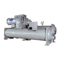
Hermetic Centrifugal Liquid Chillers 50/60 Hz With PIC II Controls and HFC-134a
Brand:
Carrier
| Category:
Chiller
| Size: 4.73 MB
Table of Contents
Safety Considerations
1
Table of Contents
2
Reset Type
2
Introduction
4
Abbreviations and Explanations
4
19XR Identification
5
Cooler
5
Chiller Familiarization
5
Chiller Information Nameplate
5
System Components
5
Condenser
5
Motor-Compressor
5
Control Panel
5
Front/Rear View
6
Factory-Mounted Starter or Variable
7
Frequency Drive (Optional)
7
Storage Vessel (Optional)
7
Refrigeration Cycle
7
Motor and Lubricating Oil
7
Cooling Cycle
7
Vfd Cooling Cycle
8
Lubrication Cycle
8
Summary
8
Details
8
Oil Reclaim System
8
Primary Oil Recovery Mode
8
Secondary Oil Recovery Method
8
Starting Equipment
9
Unit-Mounted Solid-State Starter
9
(Optional)
9
Unit-Mounted Wye-Delta Starter
10
(Optional)
10
Unit-Mounted VFD (Optional)
10
Controls
10
Definitions
10
Analog Signal
10
Discrete Signal
10
Integrated Starter Module (Ism
11
Optional
11
Optional
12
Chiller Visual Controller (CVC)
13
Components and Panel Locations
13
International Chiller Visual
13
Controller (ICVC)
13
Integrated Starter Module (Ism)
13
Chiller Control Module (CCM)
13
Oil Heater Contactor (1C)
13
Oil Pump Contactor (2C)
13
Hot Gas Bypass Contactor Relay (3C)
13
Control Transformers (T1, T2)
13
General
11
PIC II System Components
11
CVC/ICVC Operation and Menus
15
General
15
Alarms and Alerts
15
CVC/ICVC Menu Items
15
BASIC CVC/ICVC OPERATIONS (Using the Softkeys)
15
To View Status
16
Override Operations
16
Alarms and Alerts
18
Time Schedule Operation
20
To View and Change Set Points
21
Service Operation
21
Service Operation
22
Alarms and Alerts
22
PIC II System Functions
33
Capacity Control Fixed Speed
33
Capacity Control Vfd
33
Ecw Control Option
33
Control Point Deadband
33
Diffuser Control
33
Proportional Bands and Gain
33
Demand Limiting
34
Chiller Timers
34
Occupancy Schedule
34
Safety Controls
34
Shunt Trip (Option)
35
Default Screen Freeze
35
Ramp Loading
36
Capacity Override
36
High Discharge Temperature Control
36
Oil Sump Temperature Control
36
Oil Cooler
36
Remote Start/Stop Controls
36
Spare Safety Inputs
36
Alarm (Trip) Output Contacts
37
Refrigerant Leak Detector
37
Kilowatt Output
37
Remote Reset of Alarms
37
Condenser Pump Control
37
Condenser Freeze Prevention
38
Evaporator Freeze Protection (ICVC Only)
38
Tower Fan Relay Low and High
38
Auto. Restart after Power Failure
38
Water/Brine Reset
38
Demand Limit Control Option
39
Surge Prevention Algorithm
39
(Fixed Speed Chiller)
39
Surge Prevention Algorithm with VFD
40
Surge Protection VFD Units
40
Surge Protection (Fixed Speed Chiller)
40
Head Pressure Reference Output
40
Lead/Lag Control
40
Common Point Sensor Installation
41
Chiller Communication Wiring
41
Lead/Lag Operation
41
Load Balancing
41
Faulted Chiller Operation
42
Load Balancing
42
Auto. Restart after Power Failure
42
Ice Build Control
43
Ice Build Initiation
43
Start-Up/Recycle Operation
43
Temperature Control During Ice Build
43
Termination of Ice Build
43
Return to Non-Ice Build Operations
44
Attach to Network Device Control
44
Attaching to Other Ccn Modules
44
Controls
45
Service Operation
45
To Access the Service Screens
45
To Log out of Network Device
45
Holiday Scheduling
45
Start-Up/Shutdown/Recycle
46
Sequence
46
Local Start-Up
46
Shutdown Sequence
47
Automatic Soft Stop Amps Threshold
47
Chilled Water Recycle Mode
47
Safety Shutdown
47
Before Initial Start-Up
48
Job Data Required
48
Equipment Required
48
Using the Optional Storage Tank
48
And Pumpout System
48
Remove Shipping Packaging
48
Open Oil Circuit Valves
48
Tighten All Gasketed Joints and Guide Vane Shaft Packing
48
Check Chiller Tightness
48
Refrigerant Tracer
48
Leak Test Chiller
50
Standing Vacuum Test
50
Chiller Dehydration
53
Inspect Water Piping
53
Check Relief Valves
53
Inspect Wiring
53
Carrier Comfort Network Interface
54
Solid-State Starter
54
Check the Oil Heater
55
Oil Charge
55
Software Configuration
55
Check Starter
54
Input Time and Date
55
Password
55
Change CVC/ICVC Configuration
56
Change Language
56
To Change Display to Metric Units
56
To Change the Password
56
If Necessary
57
If Necessary
58
Parameters if Necessary
58
Password
58
Verify Vfd Configuration and Change
58
Vfd Chiller Field Set up and Verification
58
If Necessary
59
Necessary
59
Password
59
Password
60
VFD CONTROL VERIFICATION (Running
60
If Necessary
61
Modify Equipment Configuration
61
Password
61
And Waterside Flow Device Calibration
62
Cooler Condenser Pressure Transducer
62
Perform a Control Test
62
Charge Refrigerant into Chiller
63
Chiller Equalization Without a
63
Controls and Compressor
63
High Altitude Locations
63
Pumpout Unit
63
Initial Start-Up
64
Dry Run to Test Start-Up Sequence
65
Input the Design Set Points
55
Input Service Configurations
55
Check Motor Rotation
65
Check Oil Pressure and Compressor Stop
65
To Prevent Accidental Start-Up
65
Check Chiller Operating Condition
65
Instruct the Customer Operator
65
Cooler-Condenser
65
Operating Instructions
66
Initial Start-Up
66
Operator Duties
66
Prepare the Chiller for Start-Up
66
To Start the Chiller
66
Check the Running System
66
To Stop the Chiller
66
After Limited Shutdown
66
Preparation for Extended Shutdown
66
After Extended Shutdown
67
Cold Weather Operation
67
Manual Guide Vane Operation
67
Operating the Optional Pumpout Unit
67
Procedures
67
Pumpout and Refrigerant Transfer Procedures
67
Refrigeration Log
67
To Read Refrigerant Pressures
67
Chillers with Storage Tanks
69
Transfer Refrigerant from
69
Chiller Condenser Vessel
70
Chiller Cooler Vessel
70
Chillers with Isolation Valves
70
Transfer All Refrigerant to
70
Adding Refrigerant
71
General Maintenance
71
Procedures
71
Removing Refrigerant
71
Adjusting the Refrigerant Charge
71
Refrigerant Leak Testing
71
Leak Rate
71
Test after Service, Repair, or Major Leak
71
Standing Vacuum Test
72
Checking Guide Vane Linkage
72
Trim Refrigerant Charge
72
Weekly Maintenance
72
Check the Lubrication System
72
Scheduled Maintenance
73
Service Ontime
73
Inspect the Control Panel
73
Monthly
73
Changing Oil Filter
73
Oil Specification
73
Oil Changes
73
Refrigerant Filter
73
Oil Reclaim Filter
73
Inspect Relief Valves and Piping
74
Compressor Bearing and Gear Maintenance
74
Inspect the Heat Exchanger Tubes
74
And Flow Devices
74
Cooler and Flow Devices
74
Condenser and Flow Devices
74
Water Leaks
74
Inspect Refrigerant Float System
74
Water Treatment
75
Inspect the Starting Equipment
75
Check Pressure Transducers
75
Optional Pumpout System Maintenance
75
Optional Pumpout Compressor Oil Charge
75
Optional Pumpout Safety Control Settings
75
Ordering Replacement Chiller Parts
75
Troubleshooting Guide
76
Overview
76
Checking Display Messages
76
Checking Temperature Sensors
76
Resistance Check
76
Voltage Drop
76
Check Sensor Accuracy
76
Dual Temperature Sensors
76
Checking Pressure Transducers
76
Units Equipped with CVC
76
Transducer Replacement
77
Control Algorithms Checkout Procedure
77
Control Test
77
Troubleshooting
78
Chiller Protect Limit Faults
81
Control Modules
87
RED LED (Labeled as STAT)
87
Notes on Module Operation
87
Chiller Control Module (CCM)
88
Integrated Starter Module
88
Replacing Defective Processor Modules
88
Installation
88
Solid-State Starters
88
Testing Silicon Control Rectifiers in
88
Benshaw, Inc. Solid-State Starters
88
Scr Removal/Installation
90
Physical Data
90
Index
123
Advertisement
Advertisement
Related Products
Carrier XARIOS X 600
Carrier XARIOS X 500-04
Carrier XCT7 40VCW117FQEE
Carrier XCT7 40VU0071-7E-QEE
Carrier XCT7 40VH015A-7G-QEE
Carrier Transicold X4 7500
Carrier XCT7 40VL012R-7G-QEE
Carrier X4 7700
Carrier XCT7 40VL009R-7G-QEE
Carrier XCT7 40VH A-7G Series
Carrier Categories
Air Conditioner
Heat Pump
Furnace
Thermostat
Chiller
More Carrier Manuals
Login
Sign In
OR
Sign in with Facebook
Sign in with Google
Upload manual
Upload from disk
Upload from URL