Sign In
Upload
Manuals
Brands
Carrier TRANSICOLD Manuals
Inverter
PowerLINE Series
Carrier TRANSICOLD PowerLINE Series Manuals
Manuals and User Guides for Carrier TRANSICOLD PowerLINE Series. We have
1
Carrier TRANSICOLD PowerLINE Series manual available for free PDF download: Operation And Service Manual
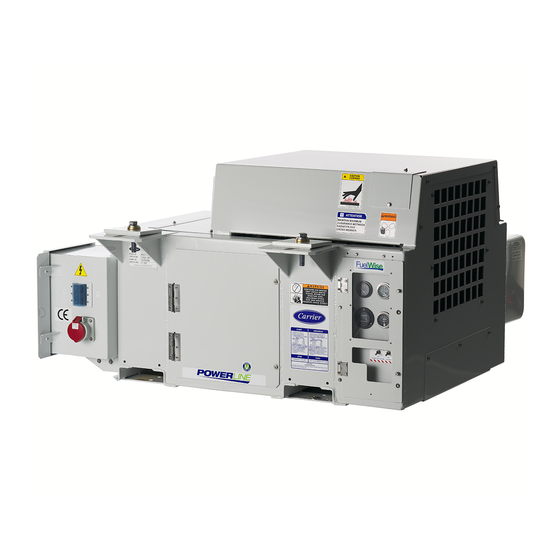
Carrier TRANSICOLD PowerLINE Series Operation And Service Manual (66 pages)
Diesel Generator Set
Brand:
Carrier TRANSICOLD
| Category:
Inverter
| Size: 8 MB
Table of Contents
Table of Contents
5
Paragraph Number
9
Safety Summary
9
General Safety Notices
9
First Aid
9
Operating Precautions
9
Maintenance Precautions
9
Specific Hazard Statements
9
Figure Number
13
Description
13
Introduction
13
Figure 2.1 Generator Set
13
Configuration Identification
14
Figure 2.2 Generator Set Components
14
Figure 2.3 Generator Set Components - Top View
15
Alternating Current Generator
16
Voltage Controller
16
Engine
16
Figure 2.4 Generator and Engine - Unidrive Assembly
16
Engine Fuel System
17
Figure 2.5 Engine Fuel System
17
Electronic Governor
18
Figure 2.6 Fuel Tank
18
Figure 2.7 Electronic Governor Module (EG)
18
Engine Lubrication System
19
Figure 2.8 Engine Lubrication System
19
Engine Air Cleaner System
20
Figure 2.9 Engine Air Cleaner
20
Engine Cooling System
21
Figure 2.10 Engine Cooling System
21
Battery and Battery Charging System
22
Control Panel and Control Box Components
22
Water Temperature Gauge
22
Oil Pressure Gauge
22
Total Time Meter (TT)
22
Ammeter (A)
22
Intake Heater Switch (HS)
22
Ignition Switch (IGN)
22
Intake Heater Timer (IHT)
22
Starter Solenoid Timer (SST)
22
Figure 2.11 Control Panel and Control Box
23
Receptacle Box Components
24
Safety Devices
24
Figure 2.12 Receptacle Box
24
Table Number
25
Table 2-1 Safety Devices
25
Unit Specifications
26
Table 2-2 Fuel Tanks
26
Table 2-3 Generator
26
Table 2-4 Engine Data
26
Operation
29
Generator Set Installation
29
Generator Set Removal
29
Figure 3.1 Generator Set Mounting - Standard Mount
29
Starting and Stopping Instructions
30
Pre-Start Inspection
30
Starting Instructions
30
Post-Start Inspection
31
Stopping Instructions
31
Sequence of Operation
31
Table 3-1 Cold Engine Preheat Times
31
Troubleshooting
33
Diesel Engine
33
Engine will Not Start
33
Table 4-1 Engine will Not Start
33
Engine Starts then Stops
34
Engine will Not Shut off
34
Starter Motor Malfunction
34
Table 4-2 Engine Starts then Stops
34
Table 4-3 Engine will Not Shut off
34
Table 4-4 Starter Motor Malfunction
34
Malfunction in the Engine Starting Circuit
35
Miscellaneous Engine Troubleshooting
35
Table 4-5 Malfunction in the Engine Starting Circuit
35
Table 4-6 Miscellaneous Engine Troubleshooting
35
Battery Charger
36
Table 4-7 Battery Charger (Solid State)
36
Alternating Current (Ac) Generator
37
Table 4-8 Alternating Current Generator
37
Electronic Governor Module
38
Voltage Controller
38
High Voltage Circuit
38
Table 4-9 Electronic Governor Modules
38
Table 4-10 Voltage Controller
38
Service and Preventative Maintenance
41
Introduction
41
Preventative Maintenance Schedule
41
Table 5-1 Preventative Maintenance Actions and Schedule
41
Battery Service
43
Engine Service and Components
43
Bleeding the Fuel System
43
Servicing Fuel Pump Internal Filter
43
Figure 5.1 Mechanical Fuel Pump
43
Fuel Filter
44
In-Line Fuel Strainer
44
Cooling System
44
Lube Oil Filter
44
Servicing Low Oil Pressure Switch
44
Engine Speed
45
Replacing the Engine Speed Sensor
45
Servicing Poly V-Belt
45
Engine Air Cleaner
45
Figure 5.2 Air Cleaner, Dry Element
46
Figure 5.3 Air Cleaner, Oil Bath
47
Engine Crankcase Breather
48
Intake Heater Test
48
Intake Heater Service
48
Figure 5.4 Engine Crankcase Breather
48
Figure 5.5 Intake Heater
48
Intake Heater Switch (HS)
49
Servicing the Ac Generator
49
Remove and Replace Procedure
49
Figure 5.6 Generator Shaft Keyway
50
Figure 5.7 Generator Coupler Bolt
51
Figure 5.8 Generator Alignment Bolt
51
Figure 5.9 Generator Mounting Bolts
52
General Generator Set Maintenance
53
Maintenance of Painted Surfaces
53
Figure 5.10 Battery Charger
53
Check and Replace Isolators / Shockmounts
54
Figure 5.11 Generator Shockmounts
55
Figure 5.12 Engine Shockmounts
56
Figure 5.13 Truss and Isolator
56
Unidrive Torque Requirements
57
Figure 5.14 Unidrive Torque Requirements
57
Schematics
59
Introduction
59
Figure 6.1 Schematic Legend for 12VDC Circuit
59
Figure 6.2 Schematic for 12 VDC Control Circuit
60
Figure 6.3 Schematic High Voltage Circuitry
61
Index
63
Advertisement
Advertisement
Related Products
Carrier TRANSICOLD PC710307
Carrier TRANSICOLD 69UG15
Carrier TRANSICOLD Categories
Refrigerator
Automobile Accessories
Portable Generator
Industrial Equipment
Air Conditioner
More Carrier TRANSICOLD Manuals
Login
Sign In
OR
Sign in with Facebook
Sign in with Google
Upload manual
Upload from disk
Upload from URL