
Subscribe to Our Youtube Channel
Related Manuals for Carrier TRANSICOLD PowerLINE Series

Summary of Contents for Carrier TRANSICOLD PowerLINE Series
- Page 1 Diesel Generator Set OPERATIONS AND SERVICE MANUAL 69UG15 ® PowerLINE Series 55 Generator Set Units PID UG5500 to 5599 EU Stage V Compliant T-375...
- Page 3 OPERATIONS AND SERVICE MANUAL 69UG15 ® PowerLINE Series 55 Generator Set Units PID UG5500 to 5599 EU Stage V Compliant © Carrier Corporation, 2021 Printed in U. S. A. March 2021...
-
Page 5: Table Of Contents
TABLE OF CONTENTS PARAGRAPH NUMBER Page SAFETY SUMMARY ..............1–1 GENERAL SAFETY NOTICES . - Page 6 TROUBLESHOOTING ..............4–1 DIESEL ENGINE .
- Page 7 LIST OF ILLUSTRATIONS FIGURE NUMBER Page Figure 2.1 Generator Set ..............2–1 Figure 2.2 Generator Set Components .
- Page 8 LIST OF TABLES TABLE NUMBER Page Table 2–1 Safety Devices ............. . . 2–13 Table 2–2 Fuel Tanks .
-
Page 9: Safety Summary
SECTION 1 SAFETY SUMMARY 1.1 General Safety Notices Installation and servicing of Genset equipment can be hazardous due to system belts, radiator fan, and electrical components. Only trained and qualified service personnel should install, repair, or service Genset equipment. When working on Genset equipment, observe all potential Danger, Warning and Caution hazards, including those shown below and on hazard labels attached to the unit. - Page 10 WARNING Beware of moving poly V-belt, belt driven components and hot exhaust components. WARNING Under no circumstances should ether or any other unauthorized starting aids be used in con- junction with the air intake heater. WARNING Beware of pinch points. WARNING Do not use gasoline to clean air cleaner parts.
- Page 11 CAUTION Always cover the engine inlet tube while the air cleaner is being serviced. CAUTION Do not underfill or overfill the oil bath cups. Overfilling of cups causes loss of capacity; under- filling cups causes lack of filtering efficiency. CAUTION Continued operation with failed shockmounts may result in engine or generator damage.
-
Page 13: Description
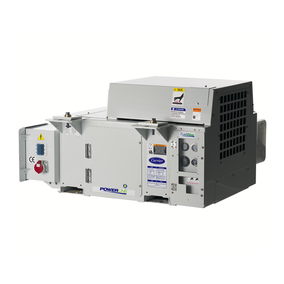
SECTION 2 DESCRIPTION 2.1 Introduction The Carrier Transicold model 69UG15 diesel-driven generator set (see Figure 2.1) provides a constant electrical power supply for all-electric refrigeration units. The 69UG15 is an under-mounted unit secured to the frame rails of the container trailer chassis. -
Page 14: Configuration Identification
2.2 Configuration Identification Generator set identification information is provided on a unit nameplate located next to the access service door (front facing). The label provides the generator set model number, serial number, and parts identification number (PID). The model number identifies the overall configuration while the PID provides information on specific optional equipment and differences in detailed parts. -
Page 15: Figure 2.3 Generator Set Components - Top View
Figure 2.3 Generator Set Components - Top View 1) Fuel Tank 7) Air Cleaner 2) Battery 8) Fuel Filter / Water Separator 3) Battery Charger 9) Oil Filter 4) AC Generator 10) Receptacle Box 5) Engine 11) Control Panel and Control Box 6) Exhaust Muffler 12) Radiator - - - - -... -
Page 16: Alternating Current Generator
2.3 Alternating Current Generator The Alternating Current (AC) Generator (see Figure 2.4) bolts directly to the engine and supplies nominal 50/60Hz power depending on the load requirement. Generator sets will start at 50Hz. Once the unit is running, the voltage controller will read the voltage output of the generator and adjust accordingly to keep the voltage within ISO limits. -
Page 17: Engine Fuel System
2.4.1 Engine Fuel System The engine fuel system (see Figure 2.5) is a closed circuit that injects a precise amount of atomized fuel into the engine cylinders. A mechanical lift pump initially transfers fuel at low pressure from the fuel tank and through the fuel shutoff valve. Fuel exits the lift pump and is pushed into the fuel filter / water separator to remove water and finer particles. -
Page 18: Electronic Governor
The engine requires all air to be removed the system in order to run at optimal performance. The fuel system contains a fuel pump primer on the mechanical lift pump and an air bleed screw after the injection pump, if bleeding air from the system is required. -
Page 19: Engine Lubrication System
2.4.3 Engine Lubrication System The engine lubrication system (see Figure 2.8) keeps the engine running smoothly, providing a supply of lubricat- ing oil to the various moving parts in the engine. The main function is to enable the formation of a film of oil between moving parts, to reduce friction and wear. -
Page 20: Engine Air Cleaner System
2.4.4 Engine Air Cleaner System The engine air cleaner system (see Figure 2.9) utilizes a filter element to filter the engine intake air. The air cleaner is designed to effectively remove contaminants from the air stream, resulting in prolonged engine life and reduced wear on all engine operating parts. -
Page 21: Engine Cooling System
2.4.5 Engine Cooling System The engine cooling system (see Figure 2.10) uses extended life coolant and a radiator to keep the engine from overheating. The radiator transfers the heat from the engine coolant to the surrounding air. The water pump and the radiator cooling fan are belt-driven from the engine crankshaft. -
Page 22: Battery And Battery Charging System
2.5 Battery and Battery Charging System The battery provides 12 VDC power to the starter motor. It also provides the initial voltage for the Intake Heater until the unit starts. The solid state battery charger is located in front of the battery. The battery charger is powered by the generator, and this input is protected by fuses located in the receptacle box. -
Page 23: Figure 2.11 Control Panel And Control Box
Figure 2.11 Control Panel and Control Box Control Panel Control Box INTAKE AIR HEATER IGNITION Mounted to back of box 1) Water Temperature Gauge 9) Intake Heater Relay (HR) 2) Oil Pressure Gauge 10) Circuit Breaker (CB2) 3) Total Time Meter (TT) 11) Circuit Breaker (CB3) 4) Ammeter (A) 12) Circuit Breaker (CB4) -
Page 24: Receptacle Box Components
2.7 Receptacle Box Components The Receptacle box (see Figure 2.12) contain components required for monitoring and controlling the Genset unit. Figure 2.12 Receptacle Box 1) Access Cover 5) Voltage Controller Fuse (VCF1) 2) Circuit Breaker (CB1) Genset 6) Voltage Controller Fuse (VCF2) 3) Receptacle 7) Battery Charger Fuse BCF3 4) Voltage Controller (VC) -
Page 25: Table 2-1 Safety Devices
Table 2–1 Safety Devices Engine Unsafe Condition: Low engine lubricating oil pressure Safety Switch Low Oil Pressure Switch (LOP) - Automatic reset Switch Setting Opens below 1.27 kg/cm Unsafe Condition: High engine cooling water temperature Safety Switch Water temperature switch (HWT) - Automatic reset Switch Setting Opens at 110°C Unsafe Condition: Excessive current draw by the safety relay, fuel heater, water temperature gauge, oil pressure gauge or total time meter... -
Page 26: Unit Specifications
2.9 Unit Specifications Table 2–2 Fuel Tanks Capacity: 50 Gallon Steel Fill Capacity: 197 liters Draw Capacity: 189 liters 50 Gallon Aluminum Fill Capacity: 197 liters Draw Capacity: 189 liters 65 Gallon Steel Fill Capacity: 256 liters Draw Capacity: 246 liters Unit Weights (with 50 Gallon Steel 729.8 kg... - Page 27 Table 2–4 Engine Data Lubrication System: Oil Pressure 3.3 to 5.2 kg/cm Oil Pressure Safety Switch 1.27 kg/cm Setting Opens Capacity Engine - 14.2 liters, includes standard filter. Oil Level Indicator Dipstick in oil pan or fill cap. NOTE: To check oil level on engines with the dipstick mounted in the fill cap, remove the cap and wipe the dipstick clean.
- Page 28 Table 2–4 Engine Data Cooling System: Capacity 5.68 liters - includes 0.95 liter in coolant recovery bottle. Anti-Freeze: Extended Life The cooling system is factory charged with a 50/ 50 mix of extended life coolant (ELC) and deionized water. This mixture provides protection to -37°C.
-
Page 29: Operation
SECTION 3 OPERATION 3.1 Generator Set Installation The generator set is mounted under the center of the trailer chassis and is easily handled with a fork lift truck capable of handling 907 kg. The fork lift pockets provided are accessible from either side. Mounting clamps are designed to be attached to outside I-beam flanges only. -
Page 30: Starting And Stopping Instructions
3.3 Starting and Stopping Instructions 3.3.1 Pre-Start Inspection 1. Check engine lubrication and fuel filters, oil lines, and connections for leaks. If required, tighten connections and / or replace gaskets. Table 2–4). 2. Check engine lubricating oil level (see 3. Check the poly V-belt for fraying or cracks and proper tension (see Section 5.4.10). -
Page 31: Post-Start Inspection
Table 3–1 Cold Engine Preheat Times Ambient Temperature Time 26°C 5 seconds 0° to 26°C 10 seconds -8° to 26°C 20 seconds Below -8°C 30 seconds 4. With the Intake Heater Switch (HS) held in the PREHEAT position, place the Ignition Switch (IGN) in the START position. -
Page 33: Troubleshooting
SECTION 4 TROUBLESHOOTING 4.1 Diesel Engine 4.1.1 Engine Will Not Start Table 4–1 Engine Will Not Start Condition Possible Cause Remedy / Reference Section Starter motor will not crank or Battery insufficiently charged Charge low cranking speed Battery terminal post or battery defective Check Electrical connections at starter are bad Correct... -
Page 34: Engine Starts Then Stops
4.1.2 Engine Starts Then Stops Table 4–2 Engine Starts Then Stops Condition Possible Cause Remedy / Reference Section Engine stops after a few No fuel in tank Table 2–4 rotations Intake heater switch not held long enough Hold switch Fuel filter restricted Replace Section 5.4.11 Air cleaner or hose restricted... -
Page 35: Malfunction In The Engine Starting Circuit
Table 4–4 Starter Motor Malfunction Condition Possible Cause Remedy / Reference Section Starter motor turns, but pinion Pinion or ring gear obstructed or worn Engine Manual does not engage Starter motor does not Ignition switch is bad Check / Replace disengage after switch has Starter motor solenoid is bad Engine Manual... -
Page 36: Battery Charger
Table 4–6 Miscellaneous Engine Troubleshooting Condition Possible Cause Remedy / Reference Section Vibration Engine shockmounts are bad Replace Poor compression Engine Manual Overheating Restriction in air cleaner Section 5.4.11 Exhaust pipe restriction Remove Restriction in water jacket Engine Manual Restriction in radiator Section 5.4.5 Coolant level too low Table 2–4... -
Page 37: Alternating Current (Ac) Generator
4.3 Alternating Current (AC) Generator Table 4–8 Alternating Current Generator Condition Possible Cause Remedy / Reference Section No voltage Loss of rotor magnetism Replace Circuit breaker tripped Check CB1 Open in stator windings Replace Short circuited Replace Contactor not engaged Replace Low voltage Low engine speed... -
Page 38: Electronic Governor Module
4.4 Electronic Governor Module Table 4–9 Electronic Governor Modules Fault LED flash code Possible Cause Engine Over Speed: more than One Long–One Short ESS or mechanical engine problem 2,530 RPM Actuator Wiring Disconnection. Two Long–One Short Short ESS or wiring problem No signal from ESS for 2 seconds after RPM is greater than 1,000 RPM for 10 seconds, OR for 5... - Page 39 Item Checks Potential Cause Receptacle (R) Check output voltage at Receptacle R (L1- Faulty Receptacle (Replace) L2, L2-L3, L1-L3) (50Hz: 360 - 460 VAC, and 60Hz: 400 - 500 VAC) High Voltage Wires (from Check if wires/terminals are connected Loose connections (Tighten) Circuit Breaker to Receptacle) (Check Continuity for each leg) Circuit Breaker (CB)
-
Page 41: Service And Preventative Maintenance
SECTION 5 SERVICE AND PREVENTATIVE MAINTENANCE 5.1 Introduction This section covers service for the generator set and general engine service. Refer to the Kubota engine workshop manual 62-10865, Section 1.1, for additional engine servicing. WARNING Beware of moving poly V-belt, belt driven components and hot exhaust components. 5.2 Preventative Maintenance Schedule A tabular listing of the recommended preventative maintenance activities and schedule is provided in Table... - Page 42 Table 5–1 Preventative Maintenance Actions and Schedule Perform Perform Perform Manual Procedure During every 2000 every 4000 Reference Pre-Trip hrs service hrs service 20. Tighten engine and generator mounting bolts. Section 5.6.2 21. Tighten all electrical connections in control box. 22.
-
Page 43: Battery Service
5.3 Battery Service When replacing the battery, determine whether the unit was supplied with a mat in the battery tray. If so equipped, the mat must also be replaced. 5.4 Engine Service and Components The unit is equipped with a mechanical fuel pump (see Figure 5.1) mounted on the engine next to the injection pump. -
Page 44: Fuel Filter
5.4.3 Fuel Filter The fuel filter is located on the generator set frame (see Figure 2.5). 1. To replace the fuel filter, loosen and remove the filter housing. 2. Lightly oil new gasket with lube oil. 3. Replace the filter. If the generator set is equipped with the fuel filter bowl assembly, when replacing the fuel filter, a new fuel filter O-ring should be oiled and replaced, and then the clear bowl should also be tightened to 24 N-m. -
Page 45: Engine Speed
3. Apply Teflon thread sealer to the threads of the new LOP switch. 4. Install the new LOP switch. 5. Reconnect harness connection to the low oil pressure switch. 5.4.8 Engine Speed 1. The engine speed is electronically controlled. Do not attempt to adjust engine speed. 5.4.9 Replacing the Engine Speed Sensor 1. -
Page 46: Figure 5.2 Air Cleaner, Dry Element
1. Check all connections for mechanical tightness. Be sure the air cleaner outlet pipe is not fractured. 2. In case of leakage, if adjustment does not correct the problem, replace necessary parts or gaskets. Swollen or distorted gaskets must always be replaced. Air Filter Indicator The air filter indicator, used with the dry element filter, is mounted on the unit frame and connected to the engine air intake. -
Page 47: Figure 5.3 Air Cleaner, Oil Bath
CAUTION Do not underfill or overfill the oil bath cups. Overfilling cups causes loss of capacity; underfill- ing cups causes lack of filtering efficiency. Figure 5.3 Air Cleaner, Oil Bath 1) Air Inlet Hood 4) Inner Oil Cup 2) Air Cleaner Body 5) Gasket 3) Cap Clamp 6) Oil Cup... -
Page 48: Engine Crankcase Breather
5.4.12 Engine Crankcase Breather The engine uses a closed type breather (see Figure 5.4) with the breather line attached to the cylinder head cover. It is not necessary to disassemble valve style elements for cleaning. However, the bleed hole should be checked for obstructions. -
Page 49: Intake Heater Switch (Hs)
5. Install the new heater with a new gasket on either side. 6. Assemble transition to heater and torque mounting hardware (refer to engine manual for torque values). 7. Reconnect the harness to heater connection point. 8. Coat the stud on the heater with protective coating. 5.4.15 Intake Heater Switch (HS) 1. -
Page 50: Figure 5.6 Generator Shaft Keyway
12. Back off about 25mm, but do not remove the engine shockmount bolts. This will allow the engine / generator to be slightly lifted off of the unit frame. The generator / engine must be slightly lifted off of the unit frame in order to provide enough clearance for the generator support plate to slide away from the unit frame. -
Page 51: Figure 5.7 Generator Coupler Bolt
Figure 20. Apply Loctite 262 to the generator coupler bolt. Install with washer and torque to 38 N-m (28 ft-lbs). See 5.7. NOTE In order to torque generator torsional dampener gear bolt, use a strap wrench or similar device to secure the dampener while torquing the bolt. -
Page 52: Figure 5.9 Generator Mounting Bolts
24. Once aligned, push the generator to fully seat the torsional dampener into the aluminum housing of the flywheel adaptor plate. 25. With the torsional dampener seated into the aluminum housing, the alignment bolts (2) can be removed, and the generator mounting bolts (12) can be reinstalled. Torque to 34 Nm (25 ft-lb). Install several mounting bolts to secure the generator before removing the alignment bolts. -
Page 53: General Generator Set Maintenance
Figure 5.10 Battery Charger 1) AC Wiring from Generator 2) DC Wiring to 12v Battery Red (+), Black (-) - - - - - 34. Re-secure the battery charger assembly to the unit frame. 35. Cut the wire-tie supporting the receptacle box to the unit frame and re-secure the receptacle box to the unit frame using bolts and washers (6). -
Page 54: Check And Replace Isolators / Shockmounts
5.6.2 Check and Replace Isolators / Shockmounts CAUTION Continued operation with failed shockmounts may result in engine or generator damage. When a shockmount has been cut, split, abraded or has flared due to normal deterioration, it must be replaced. Damage to the mounts may not be visible when installed and under load from the component. -
Page 55: Figure 5.11 Generator Shockmounts
Figure 5.11 Generator Shockmounts Install Mount with Large Flare at Top 1) Generator 12) Flat Washer (5/8) 2) Locknut (5/8) 13) Mounting Base 3) Flat Washer (5/8) 14) Locknut (1/2) 4) Support Plate 15) Flat Washer (1/2) 5) Screw (3/8) 16) Flat Washer (5/8) 6) Flat Washer (3/8) 17) Screw (5/8) -
Page 56: Figure 5.12 Engine Shockmounts
Figure 5.12 Engine Shockmounts 1) Shockmount 5) Snubbing Washer 2) Snubbing Washer 6) Shockmount 3) Bolt 7) Flat Washer 4) Lock Washer - - - - - Figure 5.13 Truss and Isolator 1) Truss 7) Locknut 2) Bolt 8) Heat Shield 3) Lock Washer 9) Isolator 4) Flat Washer... -
Page 57: Unidrive Torque Requirements
5.7 Unidrive Torque Requirements Extensive damage may occur if the proper hardware is not used and/or proper procedures are not followed when working with the unidrive assembly. Periodic inspection of hardware and bolt torque is recommended to ensure the integrity of the unidrive. Torque value and hardware requirements for unidrive assembly are provided in Figure 5.14. -
Page 59: Schematics
SECTION 6 SCHEMATICS 6.1 Introduction This section contains the 12-volt DC control circuit schematic and the high voltage circuitry schematics. Figure 6.1 Schematic Legend for 12VDC Circuit 6–1 T-375... -
Page 60: Figure 6.2 Schematic For 12 Vdc Control Circuit
Figure 6.2 Schematic for 12 VDC Control Circuit 12 VDC Control Circuit T-375 6–2... -
Page 61: Figure 6.3 Schematic High Voltage Circuitry
Figure 6.3 Schematic High Voltage Circuitry Receptacle Box High Voltage Circuitry 6–3 T-375... -
Page 63: Index
INDEX Engine Fuel System, Fuel Filter / Water Separator 2–5 Engine Fuel System, Fuel Filter Replace 5–4 AC Generator 2–1 2–4 Engine Fuel System, Fuel Pump Internal Filter Service AC Generator Service 5–9 5–3 AC Generator Troubleshooting 4–5 Engine Fuel System, Fuel Solenoid (FS) 2–6 Ammeter 2–10 Engine Fuel System, Fuel Tank Specifications 2–14 Engine Fuel System, Injection Pump 2–5... - Page 64 Isolators/Shockmounts Check and Replace 5–14 Schematic Diagram - Legend 6–1 Schematic High Voltage Circuitry 6–3 Schematics 6–1 Sequence of Operation 3–3 Low Oil Pressure Switch (LOP) Operation 3–3 Standard Mount Mounting 3–1 Starter Motor (SM) Operation 3–3 Starter Solenoid (SS) Operation 3–3 Maintenance Precautions 1–1 Starter Solenoid Timer (SST) 2–10 Starting and Stopping Instructions 3–2...
- Page 66 Carrier Transicold Division, Carrier Corporation P.O. Box 4805 Syracuse, NY 13221 USA https://www.carrier.com/container-refrigeration...
Need help?
Do you have a question about the PowerLINE Series and is the answer not in the manual?
Questions and answers