Sign In
Upload
Manuals
Brands
Carrier Manuals
Air Conditioner
NP034-074
Carrier NP034-074 Manuals
Manuals and User Guides for Carrier NP034-074. We have
2
Carrier NP034-074 manuals available for free PDF download: Controls Operation And Troubleshooting, Installation, Start-Up And Service Instructions Manual
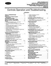
Carrier NP034-074 Controls Operation And Troubleshooting (116 pages)
Single-Package Heating/Cooling Units With Product Integrated Controls 50/60 Hz
Brand:
Carrier
| Category:
Air Conditioner Accessories
| Size: 1.83 MB
Table of Contents
Table of Contents
1
Safety Considerations
2
General
2
Architecture
2
PIC Rooftop Information
4
Digital Air Volume (DAV) Linkage
4
Major Control Components
4
General
4
PROCESSOR MODULE no . 1 (Standard)
4
Control Options Module
4
Dsio2)
4
Transducers
4
Components
4
Space Temperature Sensor (T-55)
6
SPACE TEMPERATURE SENSOR (T-56) (Use with CV
6
Indoor Air Quality (Co 2 ) Sensors
6
Outdoor Air Volume Control
7
Controls and Functions
8
Definitions
8
Accessing the Control System
9
(Hsio)
9
Keypad and Display Module (Hsio)
9
Accessing Functions and Subfunctions
11
Basic System Functions
12
Service Group
16
Schedules Group
18
Economizer and Power Exhaust Group
20
Nighttime/Unoccupied Free Cooling
21
Smoke Control Group
24
Special Ventilation Group
25
Indoor Air Quality (Iaq)
25
Dehumidification and Humidifier Group
28
Dehumidification and Reheat
28
Supply Fan Duct Pressure and VAV Control Group
29
SUPPLY FAN DUCT PRESSURE CONTROL (VAV Only)
29
SUPPLY-AIR SET POINT RESET (External Signal)
30
Remote Controls Group
31
SPACE TEMPERATURE OFFSET (CV Only)
31
Special Systems Group
31
HEAD PRESSURE/FAN CYCLING CONTROL (Motormaster® Head Pressure Control)
32
Transducers and Suction Thermistors
33
Carrier Comfort Network
33
Carrier Comfort Network (CCN) Group
33
Installation Information
34
Control Wiring
34
Smoke Control
34
Function Wiring
35
Remote SASP Reset
35
Remote START/OCCUPIED Control
35
Timed Discrete Output
41
Air Pressure Tubing
41
Space Temperature Sensors
41
Humidity Sensors
41
Interface
43
RJ-11 Plug Wiring
44
Monitor And/Or Control from Non-CCN Building Management System
44
Start-Up
46
Initial Check
46
Set Fan Status and Check Filter Switches
46
Supply Fan Status Switch (Fs)
46
Check Filter Switch (Cfs)
46
Auxiliary Switch, Power Exhaust
46
Adjusting Set Points
47
Set Point Function
49
Program Time Sequences
52
Schedule Function
52
Start Unit
53
Operating Sequences
53
Head Pressure Control
56
Control Loop Checkout
60
Unit Operation
61
Status Function
61
Troubleshooting
71
Checking Display Codes
71
Unit Standby
71
Complete Unit Stoppage
71
Single Circuit Stoppage
72
Restart Procedure
72
Alarm and Alerts
72
Diagnostic Alarm Codes and Possible Causes
72
Thermistor Troubleshooting
76
Transducer Troubleshooting
80
Refrigerant Pressure Transducer Replacement and Calibration
80
Red Led
81
Green Led
81
Processor Module (Psio1)
81
High-Voltage Relay Modules (Dsio1 and 2)
81
Control Options Module (Psio2)
83
Control Modules
81
Economizer Actuator
84
Variable Frequency Drive
84
Quick Test
86
Forcing Values
87
Service
87
History Function
87
Service Function
87
Test Function
96
Unit Control Wiring
96
Appendix A - Input/Output
103
Tables 034-078
103
Appendix B - Input/Output
105
Tables 088,104
105
Appendix C - CCN Points List
107
Appendix D - Bacnet Points List
109
Appendix E - Carrier Default Program
111
Parameter Values
111
Start-Up Checklist
113
Advertisement
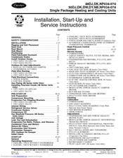
Carrier NP034-074 Installation, Start-Up And Service Instructions Manual (72 pages)
Single Package Heating and Cooling Units
Brand:
Carrier
| Category:
Air Conditioner
| Size: 1.45 MB
Table of Contents
Table of Contents
1
General
2
Safety Considerations
2
Installation
2
Rigging and Unit Placement
2
Roof Curb
2
Roof Mount
2
Slab Mount
2
Positioning
3
Field-Fabricated Ductwork
6
Condensate Drains
10
Install Outdoor Hoods
10
Unit Sizes
10
Outdoor-Air Inlet Adjustments
10
Manual Outdoor-Air Damper
10
Economizer Settings
10
Field Wire Routing
17
Unit Sizes
17
Field Electrical Connections
17
Power Wiring
17
Control Wiring
34
Gas Piping (48 Series Units Only)
36
Installing Flue/Inlet Hoods
36
Only)
37
Unit Sizes
38
Pre-Start-Up
38
Unit Preparation
38
Compressor Mounting
38
Evaporator-Fan Shipping Brackets
38
Internal Wiring
38
Refrigerant Service Valves
38
Crankcase Heaters
38
Compressor Oil
38
Units Only)
39
Unit Voltage
39
Leak Test and Dehydration
39
Evaporator-Fan Belts, Pulleys, and Sheaves
39
Condenser Fans and Motors
40
Return-Air Filters
40
Economizer Inlet Screens
40
Economizer Dampers
40
25% Outdoor-Air Damper
40
Initial Check
41
Start-Up
41
General
41
Operating Sequences
41
Cooling, Units Without Economizer
41
Heating, Units Without Economizer
41
VENTILATION AIR CIRCULATION (Continuous Fan)
42
Automatic Changeover Using Automatic
42
Head Pressure Control
42
Service
42
Service Access
42
Compressors
42
Liquid Service Valves, Filter Driers, and Sight Glasses
43
Evaporator-Fan Motors, Pulleys, and Belts
43
Power Exhaust Motors, Pulleys, and Belts
43
Unit Control Box
43
GAS HEAT SECTION (48 Series Units Only)
43
MAIN and PILOT BURNERS (48 Series Units Only)
43
FLUE GAS PASSAGEWAYS (48 Series Units Only)
43
COMBUSTION AIR BLOWER (48 Series Units Only)
43
Unit Sizes 034 and
44
ELECTRIC HEATER CONTROL BOX (50 Series Units Only)
44
Modulating Power Exhaust Damper Motor
45
Inlet Guide Vane Motor
45
Cleaning
45
Lubrication
45
Inlet Guide Vane Bearings
45
Adjustments
46
Evaporator Fan and Power Exhaust Motor Plate
46
Modulating Power Exhaust Differential
46
Inlet Guide Vane Differential Pressure
46
Switch
46
Belt Installation and Tensioning
46
Installing Alternate Motor Pulley
46
Condenser Fan Adjustment
46
AUTOMATIC PILOT ADJUSTMENT (48 Series Units Only)
49
GAS VALVE ADJUSTMENT (48 Series Units Only)
50
Main Burner Adjustment
50
Main Burner Removal (48 Series Units Only)
50
Switch Adjustment
50
Refrigerant Feed Components
50
Thermostatic Expansion Valve (TXV)
50
Moisture/Liquid Indicator
51
Filter Drier
51
Liquid Line Service Valve
51
Compressor Discharge Service Valve
51
Compressor Suction Service Valve
51
Protective Devices
51
Compressor Protection
51
Evaporator-Fan Motor Protection
51
Condenser-Fan Motor Protection
51
Relief Devices
51
Control Circuit, 115 V
52
Control Circuit, 24 V
52
Electric Heat (50 Series Units Only)
52
Gas Heat (48 Series Units Only)
52
Troubleshooting
52
Economizer
52
Economizer Motor Checkout
52
Economizer Control Board Checkout
52
Unit Control Board Checkout
53
Basic Check
53
Detailed Check
53
Start-Up Checklist
72
Advertisement
Related Products
Carrier Novello
Carrier WeatherExpert N3
Carrier WeatherExpert N6
Carrier WeatherExpert N9
Carrier WeatherExpert N4
Carrier WeatherExpert N5
Carrier N Style
Carrier Niceday 42PHQ
Carrier N4A4
Carrier N4A5S
Carrier Categories
Air Conditioner
Heat Pump
Furnace
Thermostat
Chiller
More Carrier Manuals
Login
Sign In
OR
Sign in with Facebook
Sign in with Google
Upload manual
Upload from disk
Upload from URL