Sign In
Upload
Manuals
Brands
Camus Hydronics Manuals
Boiler
DMH 751
Camus Hydronics DMH 751 Manuals
Manuals and User Guides for Camus Hydronics DMH 751. We have
1
Camus Hydronics DMH 751 manual available for free PDF download: Installation, Operation And Service Manual
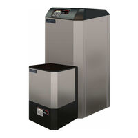
Camus Hydronics DMH 751 Installation, Operation And Service Manual (76 pages)
DynaMax SERIES GAS FIRED WALL HUNG & FLOOR MOUNT RESIDENTIAL COMMERCIAL STAINLESS STEEL BOILERS
Brand:
Camus Hydronics
| Category:
Boiler
| Size: 3.08 MB
Table of Contents
Table of Contents
2
Part 1 General Information
5
Introduction
5
Special Instructions to Owner
5
Checking Equipment
5
Display Unit
5
Sequence of Operation
5
Heat Transfer Process
6
End of Sequence
6
Installation Codes
6
Warranty
7
Removal of Existing Appliance
7
Boiler/Furnace Room Operating Condition
7
Location of Unit
8
Clearance from Combustible Material
8
Part 2 Air Inlet and Venting
12
General Venting Guide
12
Category IV Venting
12
Approved Venting Materials Category IV
13
Category II Venting
13
Approved Venting Materials Category II
13
Combined Combustion Air Inlet
13
Vent Termination and Air Inlet Clearances
14
Sidewall Venting
14
Sidewall Air Inlet
14
Vertical Direct Venting
15
Length of Air Inlet Pipe
15
Part 3 Gas Connection
16
Gas Connection
16
Gas Piping
16
Install Piping
16
Checking Gas Supply Pressure
16
Air/Gas Ratio Valve
17
Burner
17
Part 4 Water Connection
18
Freeze Protection Outdoor Installation
18
Warning Regarding Chilled Water Systems
18
Inlet and Outlet Connections
18
Minimum Pipe Size Requirements
18
Heat Exchanger
19
Low Water Temperature Systems
19
Piping Arrangements
19
Field Supplied Components
19
FLOW PROVING DEVICE (Wall Mount Models Only)
21
WATER FLOW SWITCH (Shipped Loose, Floor Mount Models Only)
21
LOW WATER CUTOFF (if Equipped)
21
Relief Valve
21
DHW TUNING VALVE (Combination Models Only)
21
Electrical Conections
22
High Limit
22
Dynamax Controller
22
Service Parts
22
Ignition Module Lockout Functions
22
Error Table
22
Hard Lockout 'A' Codes
23
Soft Lockout 'E' Codes
23
Part 5 Electrical & Controls
22
Part 6 Control Panel
24
Dynamax Controller
24
Setting the Dynamax Controller
24
Central Heating Modes
24
Domestic Hot Water Modes
25
Part 7 Components
26
Direct Spark Igniter
26
Flame Sensor
26
7.3 Combustion Air Fan
26
7.4 Gas Valve
26
7.5 Outer Jacket
26
Part 8 Labvision Software
27
8.1 Starting up Lab Vision
27
Adjusting Fan Speeds
27
Labvision Central Heating
28
Central Heating Mode, Installer Level
29
Central Heating Mode = 1, 2, 3 Installer Level
29
Labvision Domestic Hot Water
30
DHW Mode = 0, Installer Level
30
DHW Mode = 1, 2 Installer Level
30
DHW Mode = 4, Installer Level
30
Labvision Cascade
32
Data Logging
32
Analysis of Microsoft® Excel Log File
33
Error History
34
Part 9 Dynamax Control Panel
35
Introduction to the Dynamax Control Panel
36
Menu Screen
36
System Monitor Display
37
Central Heating Display
39
9.5 Domestic Hot Water Display
40
9.6 Cascade Control
41
Boiler Control
41
Error Screen
42
Part 10 Troubleshooting
43
Setting the Correct Combustion
47
Gas Valve Adjustment Procedure
47
Part 11 Maintenance
49
Examine the Venting System
49
Visually Check Main Burner Flames
49
Cleaning Boiler Heat Exchanger
49
Igniter and Flame Sensor Electrodes
50
Check Igniter Ground Wiring
50
Burner Maintenance
50
Burner Removal and Cleaning
50
Condensate Treatment
50
Condensate Volume
50
Combustion and Ventilation Air
51
Control Circuit Voltage
51
Combustible Materials
51
Freeze Protection for Indoor & Outdoor Installations
51
FREEZE PROTECTION for a HEATING BOILER SYSTEM (Optional)
51
Part 12 Installations
52
Checking the Installation
52
Checking the Construction
52
Heating Boiler Installations
52
Inspect & Recharge Condensate Collection/Neutralizing Reservoir48
52
Water Connections
52
Piping Lengths
52
Summary
52
Domestic Hot Water with Storage Tank
53
Domestic Hot Water with Plate Heat Exchanger
53
Temperature Rise at Full Firing Rate
54
Setting the Correct Combustion
55
Cascade Setup
55
Programming the Cascade Setup
55
Appliance
55
Ignition Cycle
56
Part 13 Piping Diagrams
57
Part 14 Exploded View & Parts List
63
Dynamax Wall Hung
63
Dynamax Floor Mount
64
Part 15 Electrical Diagrams
71
DM 80- 250 Internal Wiring Diagram (Wall Hung Models)
71
DM 210- 750 Internal Wiring Diagram (Floor Mount Models)
72
Field Wiring
73
System Sensor
73
Boiler Management System
73
Cascade Setup
73
Detailed Connector Description
74
Advertisement
Advertisement
Related Products
Camus Hydronics DynaMax DMH701
Camus Hydronics DynaMax DMH101
Camus Hydronics DynaMax DMH201
Camus Hydronics DynaMax DMH291
Camus Hydronics DynaMax DMH151
Camus Hydronics DynaMax DMH802
Camus Hydronics DynaMax DMH803
Camus Hydronics DynaMax DMH203
Camus Hydronics DynaMax DMH202
Camus Hydronics DynaMax DMH801
Camus Hydronics Categories
Boiler
Water Heater
Gas Heater
Controller
More Camus Hydronics Manuals
Login
Sign In
OR
Sign in with Facebook
Sign in with Google
Upload manual
Upload from disk
Upload from URL