Sign In
Upload
Manuals
Brands
BW Technologies Manuals
Control Unit
IntelliDoX
BW Technologies IntelliDoX Manuals
Manuals and User Guides for BW Technologies IntelliDoX. We have
1
BW Technologies IntelliDoX manual available for free PDF download: User Manual
BW Technologies IntelliDoX User Manual (105 pages)
Docking Module
Brand:
BW Technologies
| Category:
Control Unit
| Size: 2 MB
Table of Contents
Intellidox
2
Table of Contents
2
About this Publication
4
Important Safety Information: Read First
5
Getting Started
6
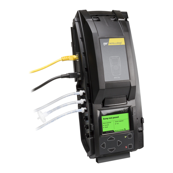
About the Intellidox Docking Module
7
Normal Operating Conditions
7
Parts and Accessories
7
Warranty Registration
7
What's in the Box
8
Intellidox Enabler Kit
8
Fleet Manager II Software
8
Intellidox at a Glance
9
Inlet Keys
10
Single-Inlet Key
11
Multi-Inlet Key
11
LCD Screen
12
Screen Color
12
Keypad
13
Keypad Buttons
13
Assemble Modules
14
Work Plan: Assemble Individual Modules
15
Work Plan: Assemble Gangs of up to Five Connected Modules
16
Assemble the Stand
17
Assembling the Stand
17
Connect Modules
18
Connecting Modules
18
Disconnecting Modules
18
Mount on a Wall
19
Before You Begin
19
Mounting Individual Modules on a Wall
20
Removing an Individual Module from a Mounted Back Panel
20
Mounting Connected Modules on a Wall
21
Removing Connected Modules from Mounted Back Panels
22
Mount on Parallel DIN Rails
23
What Is a DIN Rail
23
Before You Begin
23
Mounting Modules on Parallel DIN Rails
24
Removing an Individual Module from Parallel DIN Rails
25
Removing Connected Modules from Parallel DIN Rails
25
Prepare Modules for Use
26
Attach the End Plate
27
Attaching the End Plate
27
Removing the End Plate
27
Connect the Exhaust Tubing
28
Connecting the Exhaust Tubing
28
Connect the Inlet Filter
29
Connecting the Inlet Filter
29
Insert the Inlet Plugs
30
Connect the Power
31
Connecting the Power
31
Disconnecting the Power
31
Connect the Module to a Network
32
Before You Begin
32
Connecting the Module to a Network
33
Managing Network Settings through an Internet Browser
34
Default User Name and Password for Internet Browser Access
34
Managing Network Settings through Fleet Manager II Software
35
Connect a Calibration Gas Cylinder
36
Before You Begin
36
Connecting a Calibration Gas Cylinder
37
Dock Station Settings Menu
38
Display the Adjust Dock Station Settings Menu
39
Display the Dock Station Settings Menu
39
Displaying the Dock Station Settings Menu
39
Adjust the LCD Brightness
40
Adjusting LCD Brightness
40
Adjust Date and Time Settings
41
Adjusting Time and Date Via the Module Settings Menu
41
Configure Gas Inlets
42
Configuring Gas Inlets
42
Display the Select Language Menu
44
Display the about Summary Screen
45
Displaying the about Summary Screen
45
Detector Operations
46
Insert a Detector
47
Detector Operations Menu
48
Bump Test
49
Before You Begin
49
Bump Test Guidelines
49
Special Considerations for Intellidox Ultra
50
Fastbump
51
Standard Bump Testing
52
Calibration
53
Before You Begin
53
Calibration Guidelines
53
Calibrating a Detector
54
Transfer Datalogs from a Detector
56
Transferring Datalogs Via the Detector Operations Menu
56
Transferring Datalogs Automatically by Configuring Settings Via Fleet Manager II Software
56
Display the Adjust Dock Station Settings Menu
57
Charge a Detector
58
Charging a Detector
58
Configure Settings Via Fleet Manager II Software
59
Protect Module Operations with a Passcode
60
Configuring a Module Passcode
60
Configure Module and Detector Settings
61
Workflow: Configuring Settings
61
Creating a Configuration File Via Fleet Manager II
61
Transferring the Configuration File to a Module Via Fleet Manager II
62
Transferring the Configuration File to a Module Via USB Flash Drive
63
Transferring Configuration Settings to a Detector
63
Adjust Time and Date Settings Via Fleet Manager II Software
64
Setting the Module Time
64
Adjusting the Clock for Daylight Savings Time
66
Hibernation
67
Configure Hibernation
68
Work Plan: Configuring Hibernation
68
Creating a Hibernation Configuration File
69
Transferring a Hibernation Configuration File to a Module Via Fleet Manager II Software
70
Transferring a Hibernation Configuration File to a Module Via USB Flash Drive
70
Activating Detector Hibernation
71
Transfer Data Files
72
Transfer Data Files from the Module
73
Transferring Data Files Via Fleet Manager II Software
73
Scheduling Automatic Data File Transfers Via Fleet Manager II Software
74
Transferring Data Files Manually Via USB Flash Drive
74
Update Firmware
75
Update Module Firmware
76
Updating Module Firmware Via USB Flash Drive
76
Updating Module Firmware Via Fleet Manager II
77
Update Detector Firmware
78
Work Plan: Updating Detector Firmware
78
Transferring Detector Firmware Via USB Flash Drive
78
Transferring Detector Firmware Via Fleet Manager II
79
Updating the Detector Firmware
79
Replace Detector Cradle and Calibration Insert
80
Upgrade the Intellidox to Fit Compatible Detectors
80
What You Need to Replace the Detector Cradle and Calibration Insert
80
Replace the Detector Cradle
81
Replace the Calibration Insert
83
Maintenance
85
Clean and Maintain the Module
86
Before You Begin
86
Basic Maintenance
86
Replacement Parts and Accessories
86
Calibration Equipment and Gases
87
Technical Specification and Warranty
88
Technical Specification
89
Limited Warranty and Limitation Liability
91
Troubleshooting
92
Compliance Tests
93
The Sensor Test Fails During Bump Test or Calibration
93
The Audible Alarm Test Fails During Bump Test or Calibration
93
The Visual Alarm Test Fails During Bump Test or Calibration
93
Detectors Fail to Zero
94
Detectors
95
The Detector Firmware Is Not Updated after a New Firmware Update File Is Transferred Via USB Flash Drive
95
The Detector Time Is Incorrect, or Is Not the same as the Module Time
95
Daylight Savings Time DID Not Work
95
Modules
96
Modules Do Not Assemble into a Gang
96
Modules Do Not Attach to Mounting DIN Rails
96
Modules in a Gang Do Not Activate When the Power Is Connected
96
You Smell Gas in the Vicinity of the Module
96
The LCD Changes to Red and a Pump Alarm Error Message Is Displayed
96
The LCD Changes to Red and a Hardware Error Message Is Displayed
97
The Module Does Not Recognize a USB Flash Drive
97
The Module Configuration Is Not Updated When a New Configuration File Is Transferred Via USB Flash Drive
97
The Module Displays the Message Firmware Not Supported
97
The Module Firmware Is Not Updated When a New Firmware Update File Is Transferred from USB Flash Drive
98
The Module Firmware Is Not Updated on Modules that Are Connected in a Gang
98
Network Connections
99
The Login Web Page Does Not Display
99
Calibration of PID Sensor
100
Glossary
101
Contact BW Technologies
104
Advertisement
Advertisement
Related Products
BW Technologies Categories
Security Sensors
Gas Detectors
Measuring Instruments
Security System
Test Equipment
More BW Technologies Manuals
Login
Sign In
OR
Sign in with Facebook
Sign in with Google
Upload manual
Upload from disk
Upload from URL