Table of Contents
Advertisement
Advertisement
Chapters
Table of Contents

Summary of Contents for BW Technologies IntelliDoX
- Page 1 IntelliDoX User Manual...
-
Page 2: Table Of Contents
About this Publication ........................... 3 Important Safety Information: Read First ....................4 Getting Started ............................... 5 About the IntelliDoX Docking Module ....................6 What’s in the Box ..........................7 IntelliDoX at a Glance ........................8 ... - Page 3 Compliance Tests ..........................92 Detectors ............................94 Modules ............................95 Network Connections ........................98 Calibration of PID Sensor ........................ 99 Glossary ..............................100 Contact BW Technologies ......................... 103 BW TECHNOLOGIES BY HONEYWELL PAGE 2 OF 103...
-
Page 4: About This Publication
In no event is BW Technologies liable to anyone for any indirect, special or consequential damages. The information and specifications in this document are subject to change without notice. -
Page 5: Important Safety Information: Read First
This IntelliDoX module is intended for use as a stand-alone docking module, or as a component Do not use calibration gas cylinders past their in a connected gang of up to five IntelliDoX expiration date. -
Page 6: Getting Started
This section contains information and illustrations related to the module and its components. It also includes an overview of the module settings menu and general instructions for inserting a detector and using the detector operations menu on the module. Contents About the IntelliDoX Docking Module ......................6 Normal Operating Conditions ......................6 ... -
Page 7: About The Intellidox Docking Module
USER MANUAL || GETTING STARTED About the IntelliDoX Docking Module The IntelliDoX Docking Module (‘the module’) is an automatic test and calibration station for use with portable gas detectors manufactured by BW Technologies. The module automatically performs essential procedures including sensor identification, bump tests, calibrations, alarm tests and data transfers. -
Page 8: What's In The Box
One module with a factory-installed nest for a compatible portable gas detector, a single-inlet key, and an attached end plate; NOTE: If the end plate is not attached to the IntelliDoX docking module or is missing, contact BW Technologies or an authorized distributor immediately. -
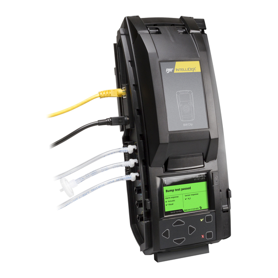
Page 9: Intellidox At A Glance
INTELLIDOX DOCKING MODULE USER MANUAL || GETTING STARTED IntelliDoX at a Glance BW TECHNOLOGIES BY HONEYWELL PAGE 8 OF 103... -
Page 10: Inlet Keys
When the single-inlet key is inserted into a module, gas inlet 1 is active and gas inlets 2, 3 and 4 are inactive. Gas Cylinder with a Single-Inlet Key When you connect a gas cylinder to IntelliDoX with a single-inlet key, you will see one connected gas type on the LCD screen: Single-inlet key: IntelliDoX... -
Page 11: Single-Inlet Key
When a multi-inlet key is inserted into a module, gas inlets 1, 2 3 and 4 are active. Connected Gas Cylinders with a Multi-Inlet Key When you connect multiple gas cylinders to IntelliDoX with a multi-inlet key, you will see multiple connected gas types on the LCD screen:... -
Page 12: Lcd Screen
INTELLIDOX DOCKING MODULE USER MANUAL || GETTING STARTED LCD Screen Screen Color BW TECHNOLOGIES BY HONEYWELL PAGE 11 OF 103... -
Page 13: Keypad
INTELLIDOX DOCKING MODULE USER MANUAL || GETTING STARTED Keypad Keypad Buttons Scroll right Scroll left Scroll up Scroll down Press and hold until the module settings menu is displayed. Press and release to select a menu item or save changes. -
Page 14: Assemble Modules
INTELLIDOX DOCKING MODULE USER MANUAL || ASSEMBLE MODULES Assemble Modules This section contains work plans and instructions for assembling and installing individual modules and gangs of up to five modules. Contents Work Plan: Assemble Individual Modules ....................14 Work Plan: Assemble Gangs of up to Five Connected Modules ............. 15 ... -
Page 15: Work Plan: Assemble Individual Modules
INTELLIDOX DOCKING MODULE USER MANUAL || ASSEMBLE MODULES Work Plan: Assemble Individual Modules Follow these steps to assemble and prepare an individual module for first-time use: Place the module and component parts on a clean, dry work surface. Verify that the appropriate inlet key is inserted. Replace the inlet key if necessary. For more information, see Inlet Keys on page 9. -
Page 16: Work Plan: Assemble Gangs Of Up To Five Connected Modules
INTELLIDOX DOCKING MODULE USER MANUAL || ASSEMBLE MODULES Work Plan: Assemble Gangs of up to Five Connected Modules Up to five modules may be connected to form a gang. Connected modules share the power supply, exhaust tubing, inlet filter, connected test gas cylinders and network connection. -
Page 17: Assemble The Stand
Pinch the arms of the metal brace together to release the ends. If the metal brace is damaged or missing, contact BW Technologies or an authorized distributor. Attach the back panel at the hinged joint. Align the hinges on the module with the hinge pins on the back panel. -
Page 18: Connect Modules
INTELLIDOX DOCKING MODULE USER MANUAL || ASSEMBLE MODULES Connect Modules Up to 5 modules may be connected to form a gang. Connected modules share a power supply, network connection, exhaust tubing, inlet filter assemblies, and connected calibration gas cylinders. Connecting Modules Assemble the stand for each module you plan to connect. -
Page 19: Mount On A Wall
Mount on a Wall You can use the back panel to mount the module securely to a wall. Because wall materials vary, mounting hardware is not provided. BW Technologies strongly recommends that wall-mounting is performed by a qualified installation contractor. -
Page 20: Mounting Individual Modules On A Wall
INTELLIDOX DOCKING MODULE USER MANUAL || ASSEMBLE MODULES Mounting Individual Modules on a Wall Prepare the modules for mounting. Disconnect modules that are connected into gangs. Disconnect the power cord, network cable, tubing and inlet filter assemblies. Remove the end plate. -
Page 21: Mounting Connected Modules On A Wall
INTELLIDOX DOCKING MODULE USER MANUAL || ASSEMBLE MODULES Mounting Connected Modules on a Wall Prepare the modules for mounting. Disconnect modules that are connected into gangs. Disconnect the power cord, network cable, tubing and inlet filter assemblies. Remove the end plate. -
Page 22: Removing Connected Modules From Mounted Back Panels
For best results, BW Technologies recommends that you hold the remainder of the gang firmly in position while pushing to help protect the remaining modules in the gang from excessive movement or falls. -
Page 23: Mount On Parallel Din Rails
Space the DIN rails 15.2 centimeters (6 inches) apart on center. BW Technologies strongly recommends using a DIN rail end plate when mounting in a vehicle, or when lateral motion is possible, or when attaching the first module in a ganged system. -
Page 24: Mounting Modules On Parallel Din Rails
INTELLIDOX DOCKING MODULE USER MANUAL || ASSEMBLE MODULES Mounting Modules on Parallel DIN Rails Prepare the modules for mounting. Disconnect modules that are connected into gangs. Disconnect the power cord, network cable, tubing and inlet filter assemblies. Remove the end plate. -
Page 25: Removing An Individual Module From Parallel Din Rails
INTELLIDOX DOCKING MODULE USER MANUAL || ASSEMBLE MODULES Removing an Individual Module from Parallel DIN Rails Disconnect the power cord, network cable, tubing and inlet filter assemblies. Remove the end plate. Find the DIN mount lock on the lower right side of the module. -
Page 26: Prepare Modules For Use
INTELLIDOX DOCKING MODULE USER MANUAL || PREPARE MODULES FOR USE Prepare Modules for Use This section contains instructions and information related to preparing modules for use. The following topics are included: Contents Attach the End Plate ............................ 26 Attaching the End Plate ........................26 ... -
Page 27: Attach The End Plate
INTELLIDOX DOCKING MODULE USER MANUAL || PREPARE MODULES FOR USE Attach the End Plate The end plate must be attached and locked with the latch arm before connecting power supply or connecting gas cylinders. The end plate must remain securely latched at all times during operation. -
Page 28: Connect The Exhaust Tubing
USER MANUAL || PREPARE MODULES FOR USE Connect the Exhaust Tubing Each IntelliDoX Enabler Kit includes tubing that may be cut to a length that is appropriate for the exhaust inlet. The maximum recommended exhaust tubing length is 15 meters (49.5 feet). -
Page 29: Connect The Inlet Filter
USER MANUAL || PREPARE MODULES FOR USE Connect the Inlet filter Each IntelliDoX Enabler Kit contains inlet filters. Unless otherwise specified, the purge inlet is configured to use ambient air in a fresh air environment with a normal atmosphere of 20.9% v/v O that is free of hazardous gas. -
Page 30: Insert The Inlet Plugs
USER MANUAL || PREPARE MODULES FOR USE Insert the Inlet Plugs Each IntelliDoX Enabler Kit contains inlet plugs. Verify that an inlet plug is inserted into each unused gas inlet before using the module. Once inserted, the inlet plugs help to protect the module from dust ingress. -
Page 31: Connect The Power
USER MANUAL || PREPARE MODULES FOR USE Connect the Power Each IntelliDoX Enabler Kit contains one power supply and AC power cord. Use only the power supply provided in the Enabler Kit to connect the module to an appropriate electrical power outlet. When the power is connected, the module activates and a self-test is performed. -
Page 32: Connect The Module To A Network
Network Passcode To prevent product tampering on IntelliDoX there is now a Network Passcode menu. To be granted access to this menu, the user needs to first enter the Module Passcode. This UI password requirement is designed to stop unauthorized access to view or change the Network Passcode. -
Page 33: Connecting The Module To A Network
For newer Fleet Manager versions, Fleet Manager will require entering the Network Passcode in order to add IntelliDoX. This will be a one time only process. Fleet Manager will need to send the IntelliDoX the network passcode to verify the connection. -
Page 34: Managing Network Settings Through An Internet Browser
Technologies recommends that you change the password for each networked module. Default User Name and Password for Internet Browser Access The user name and password are case sensitive. BW Technologies recommends that you change the password for each networked module. -
Page 35: Managing Network Settings Through Fleet Manager Ii Software
To change the password, type the old password. Type a new password, and then type the new password again. Click Save to save your settings and return to the IntelliDoX Login webpage, or click Cancel Changes to abandon the changes and return to the IntelliDoX Login webpage. -
Page 36: Connect A Calibration Gas Cylinder
USER MANUAL || PREPARE MODULES FOR USE Connect a Calibration Gas Cylinder The IntelliDoX Enabler Kit includes tubing and quick connect fittings that are appropriate for use with calibration gas cylinders that are approved for use with this product. For best results, BW Technologies recommends that the tubing is between 39 inches (1 meter) and 33 feet (10 meters) in length for calibration gas cylinders. -
Page 37: Connecting A Calibration Gas Cylinder
3/16 inch (9.5 millimeter) I.D. tubing to the demand flow regulator. Cut 1/8 inch (3.2 millimeter) I.D. tubing to an appropriate length. BW Technologies recommends that the tubing is between 39 inches (1 meter) and 33 feet (10 meters) in length. -
Page 38: Dock Station Settings Menu
INTELLIDOX DOCKING MODULE USER MANUAL || DOCK STATION SETTINGS MENU Dock Station Settings Menu This section contains information and instructions for using the Dock Station Settings menu. Contents Display the Dock Station Settings Menu ....................38 Displaying the Dock Station Settings Menu ..................38 ... -
Page 39: Display The Adjust Dock Station Settings Menu
INTELLIDOX DOCKING MODULE USER MANUAL || DOCK STATION SETTINGS MENU Display the Adjust Dock Station Settings Menu Display the Adjust dock station settings menu when you want to: Adjust the brightness of the LCD screen; Change date and time settings for the module;... -
Page 40: Adjust The Lcd Brightness
INTELLIDOX DOCKING MODULE USER MANUAL || DOCK STATION SETTINGS MENU Adjust the LCD Brightness When you adjust and save the settings for one module in a gang, the settings for all of the modules in the gang are also changed. -
Page 41: Adjust Date And Time Settings
INTELLIDOX DOCKING MODULE USER MANUAL || DOCK STATION SETTINGS MENU Adjust Date and Time Settings Follow these instructions when you want to adjust the module time and date settings manually via the Adjust dock station settings menu. When you adjust and save the settings for one module in a gang, the settings for all of the modules in the gang are also changed. -
Page 42: Configure Gas Inlets
INTELLIDOX DOCKING MODULE USER MANUAL || DOCK STATION SETTINGS MENU Configure Gas Inlets For each attached calibration gas cylinder, you must configure the gas blend, and then configure each gas type and concentration contained in the gas blend. You may also record the lot number of the calibration gas cylinder. - Page 43 INTELLIDOX DOCKING MODULE USER MANUAL || DOCK STATION SETTINGS MENU Configure the gas type for the blend. To configure a gas type in a multi-gas blend, select Gas blend from the Inlet edit menu, and then press to select one of the gases available in the blend.
-
Page 44: Display The Select Language Menu
INTELLIDOX DOCKING MODULE USER MANUAL || DOCK STATION SETTINGS MENU Display the Select Language Menu Use the Select Language menu to change the docking station's display language. You can select English, French, German, Spanish, or Portuguese. Press and hold on the keypad until... -
Page 45: Display The About Summary Screen
INTELLIDOX DOCKING MODULE USER MANUAL || DOCK STATION SETTINGS MENU Display the About Summary Screen The About information screen displays summary information about the module that may be helpful when you install or configure modules, such as: Module serial number;... -
Page 46: Detector Operations
Bump Test ..............................48 Before You Begin ..........................48 Bump Test Guidelines ........................48 Special Considerations for IntelliDoX Ultra ..................49 FastBump ............................50 Standard Bump Testing ........................51 Calibration ..............................52 Before You Begin ..........................52 ... -
Page 47: Insert A Detector
INTELLIDOX DOCKING MODULE USER MANUAL || DETECTOR OPERATIONS Insert a Detector Verify that the detector is compatible with the module. The detector model must match the model displayed on the module lid. Activate the detector if necessary. If you plan to perform compliance tests, then activate the detector and verify it is in normal operating mode prior to insertion. -
Page 48: Detector Operations Menu
INTELLIDOX DOCKING MODULE USER MANUAL || DETECTOR OPERATIONS Detector Operations Menu After the detector is recognized and automated procedures are completed, the detector operations menu and What do you need to do? are displayed. Press on the module keypad to select a menu item, and then follow on-screen instructions to perform the selected procedure. -
Page 49: Bump Test
Do not operate the module in a hazardous area. Failure to adhere to this guideline can result in possible personal injury and/or property damage. The use of gas cylinders other than those specified by BW Technologies may result in unsafe bump tests or possible non-recoverable failure of the equipment, and will invalidate the warranty. -
Page 50: Special Considerations For Intellidox Ultra
When Pre-Conditioning of the system is required please follow the procedure described below: In an IntelliDoX the only means of flowing the gas is with a bump test or calibration. To bump test Ultra for CL2/NH3 in an IntelliDoX place unit in the dock Select bump test using the IntelliDoX menu ... -
Page 51: Fastbump
INTELLIDOX DOCKING MODULE USER MANUAL || DETECTOR OPERATIONS FastBump When IntelliDoX is set to FastBump, you see at the top right of the LCD screen. FastBump is an accelerated compliance test that confirms a detector’s ability to respond to target gases by exposing the detector to a known gas concentration. When a compatible detector is inserted into the configured module, FastBump and event log transfers begin automatically after the detector is recognized. -
Page 52: Standard Bump Testing
INTELLIDOX DOCKING MODULE USER MANUAL || DETECTOR OPERATIONS Standard Bump Testing During a standard bump test, the bump procedure and other procedures configured to occur automatically on insertion are performed. You must use Fleet Manager II software to configure the module to automatically bump test a compatible detector on insertion. -
Page 53: Calibration
Do not operate the module in a hazardous area. Failure to adhere to this guideline can result in possible personal injury and/or property damage. The use of calibration gas cylinders other than those specified by BW Technologies may result in unsafe calibration or possible non-recoverable failure of the equipment, and will invalidate the warranty. -
Page 54: Calibrating A Detector
ICON and on the Ultra detector cal date and cal status is updated as pass. NOTE: If only one inlet is configured a missing gas screen will be shown by the IntelliDoX at unit insertion. 2-point calibration for PID sensor: In the Fleet manager tool disable 3-point calibration option for PID under BW Ultra configuration tab and save this configuration on Ultra detector. - Page 55 INTELLIDOX DOCKING MODULE USER MANUAL || DETECTOR OPERATIONS You may use Fleet Manager II software to configure a detector to automatically perform calibration on insertion if the sensor calibration is overdue. When a compatible detector is inserted into the module and the calibration is overdue, then calibration starts automatically once the detector is recognized.
-
Page 56: Transfer Datalogs From A Detector
INTELLIDOX DOCKING MODULE USER MANUAL || DETECTOR OPERATIONS Transfer Datalogs from a Detector There are two ways to transfer datalogs from a detector to the module: Manually, via the module operations menu, or Automatically, by configuring detector settings via Fleet Manager II software. -
Page 57: Display The Adjust Dock Station Settings Menu
INTELLIDOX DOCKING MODULE USER MANUAL || DETECTOR OPERATIONS Display the Adjust Dock Station Settings Menu Insert a compatible detector into the module. Detector identification is displayed on the LCD. After the detector is recognized, procedures specified to occur automatically on insertion are performed. -
Page 58: Charge A Detector
INTELLIDOX DOCKING MODULE USER MANUAL || DETECTOR OPERATIONS Charge a Detector You may use the module to charge compatible detectors that are fitted with rechargeable batteries. For more information on battery maintenance, refer to the appropriate detector operator manual. Charge only in a normal environment that is 20.9% v/v O and free of hazardous gas. -
Page 59: Configure Settings Via Fleet Manager Ii Software
INTELLIDOX DOCKING MODULE USER MANUAL || CONFIGURE SETTINGS VIA FLEET MANAGER II SOFTWARE Configure Settings via Fleet Manager II Software Certain features, options and settings related to module or detector operations can be configured via Fleet Manager II software. This section contains general instructions for creating and transferring configuration files to modules and detectors via Fleet Manager II software. -
Page 60: Protect Module Operations With A Passcode
Select the tab for a compatible detector, and then select the IntelliDoX Configuration tab for the compatible detector. In the IntelliDoX Operations section, select the operations you want to protect with a passcode. In the IntelliDoX Passcode section, click to select a 4-digit number. -
Page 61: Configure Module And Detector Settings
Select Configure Devices via IntelliDoX on the Devices menu. The IntelliDoX Configuration Selection dialog box is displayed. Select a configuration file and click OK. The IntelliDoX Device Configuration dialog box is displayed. Select the tab for a compatible detector, and then select the detector configuration tab. -
Page 62: Transferring The Configuration File To A Module Via Fleet Manager Ii
Transferring the Configuration File to a Module via Fleet Manager II Create the configuration file. See Configure Module and Detector Settings on page Click Save to IntelliDoX. The IntelliDoX Selection dialog box is displayed. Select one or more modules, and then click OK to transfer the configuration file to the selected modules. -
Page 63: Transferring The Configuration File To A Module Via Usb Flash Drive
INTELLIDOX DOCKING MODULE USER MANUAL || CONFIGURE SETTINGS VIA FLEET MANAGER II SOFTWARE Verify that the configuration settings are updated. Repeat steps 3 through 6 until configuration settings are verified for all modules. Transferring the Configuration File to a Module via USB Flash Drive For connected modules, transfer the configuration file to each appropriate module in the gang. -
Page 64: Adjust Time And Date Settings Via Fleet Manager Ii Software
Select Configure Devices via IntelliDoX on the Devices menu. The IntelliDoX Configuration Selection dialog box is displayed. Select a configuration file and click OK. The IntelliDoX Device Configuration dialog box is displayed. Select the tab for a compatible detector, and then select the IntelliDoX Configuration tab. - Page 65 If the date is incorrect, change the date on the PC. If the time is incorrect, click on the Time zone selector to select a different time zone. When the correct date and time are displayed, click Set IntelliDoX Time. The IntelliDoX Time Confirmation dialog box is displayed.
-
Page 66: Adjusting The Clock For Daylight Savings Time
Set the module time. See Setting the Module Time on page 63. Select the tab for a compatible detector and then select the IntelliDoX Configuration tab for the compatible detector. -
Page 67: Hibernation
USER MANUAL || HIBERNATION Hibernation Hibernation is a factory-installed feature that is available for certain detectors manufactured by BW Technologies. When hibernation is activated, all detector safety functions are disabled and the detector operating life countdown is suspended. Hibernation may extend the service life of the detector, limited by the specified maximum operating life of the detector. -
Page 68: Configure Hibernation
INTELLIDOX DOCKING MODULE USER MANUAL || HIBERNATION Configure Hibernation You must use Fleet Manager II software to create a configuration file to activate hibernation on insertion. After the configuration file is created, you can use Fleet Manager II software or a USB flash drive to transfer the file to one or more modules. When a module is configured to activate hibernation on insertion, the LCD changes to gray and the hibernation symbol is displayed. -
Page 69: Creating A Hibernation Configuration File
Select Configure Devices via IntelliDoX on the Devices menu. The IntelliDoX Configuration Selection dialog box is displayed. Select a configuration file and click OK. The IntelliDoX Device Configuration dialog box is displayed. Select the tab for a compatible detector that supports hibernation, and then select the IntelliDoX Configuration tab. -
Page 70: Transferring A Hibernation Configuration File To A Module Via Fleet Manager Ii Software
II Software Create the hibernation configuration file. See Hibernation on page Click Save to IntelliDoX. The IntelliDoX Selection dialog box is displayed. Select one or more modules, and then click OK to transfer the hibernation configuration file to the selected modules. -
Page 71: Activating Detector Hibernation
INTELLIDOX DOCKING MODULE USER MANUAL || HIBERNATION Activating Detector Hibernation Verify that the module is configured for hibernation. The LCD is gray. The hibernation symbol is displayed. Insert a compatible detector into the module. Detector identification is displayed on the LCD. -
Page 72: Transfer Data Files
INTELLIDOX DOCKING MODULE USER MANUAL || TRANSFER DATA FILES Transfer Data Files This section contains information and instructions related to transferring data files from detectors to modules and from modules to a PC via Fleet Manager II software or USB flash drive. -
Page 73: Transfer Data Files From The Module
Start Fleet Manager II software, and then log in as an administrator. Select Import from the Devices menu. The Import Device Data window is displayed. Select IntelliDoX Import. The Getting list of IntelliDoXs message box may be displayed while Fleet Manager II prepares a list of available modules. -
Page 74: Scheduling Automatic Data File Transfers Via Fleet Manager Ii Software
After the module information is gathered, the Scheduled Import dialog box is displayed. Select one or more modules from the Available IntelliDoX list, and then click Add to Schedule. The selected modules are added to the Scheduled IntelliDoX list. Set the date, time and occurrence options under Next Scheduled For. -
Page 75: Update Firmware
USER MANUAL || UPDATE FIRMWARE Update Firmware BW Technologies is committed to continuously improving product features and performance. As a result, firmware updates may become available for certain products. BW Technologies recommends that you visit the appropriate product site at www.honeywellanalytics.com... -
Page 76: Update Module Firmware
Do not deactivate the module during installation. After the update is installed, updated modules restart automatically. IntelliDoX reboot pending. Please wait… is displayed. After a few minutes, IntelliDoX rebooting is displayed. The reboot takes about 5 seconds. The screen deactivates briefly while the module restarts. -
Page 77: Updating Module Firmware Via Fleet Manager Ii
Select the downloaded file, and then click Open. The IntelliDoX Selection dialog box is displayed. Select one or more IntelliDoX modules, and then click OK. A progress screen is displayed while the firmware update file is automatically transferred to the selected modules. -
Page 78: Update Detector Firmware
BW Technologies is committed to continuously improving product features and performance. As a result, firmware updates for detectors may become available. BW Technologies recommends that you visit the appropriate product site at www.honeywellanalytics.com to find and download the latest firmware version for your modules. -
Page 79: Transferring Detector Firmware Via Fleet Manager Ii
Select the downloaded file, and then click Open. The IntelliDoX Selection dialog box is displayed. Select one or more IntelliDoX modules, and then click OK. A progress screen is displayed while the firmware update file is automatically transferred to the selected modules. -
Page 80: Replace Detector Cradle And Calibration Insert
INTELLIDOX DOCKING MODULE USER MANUAL || REPLACE DETECTOR CRADLE AND CALIBRATION INSERT Replace Detector Cradle and Calibration Insert This section contains information and instructions related to replacing an IntelliDoX detector cradle and calibration insert. Contents Replace Detector Cradle and Calibration Insert ..................79 ... -
Page 81: Replace The Detector Cradle
USER MANUAL || REPLACE DETECTOR CRADLE AND CALIBRATION INSERT Replace the Detector Cradle To replace the cradle, remove the cradle from the IntelliDoX (unscrew the screws and unplug the connector), and then install the replacement cradle. Disconnect the power cord, network cable, tubing, and inlet filter assemblies from the IntelliDoX. - Page 82 Get the replacement cradle. Plug the replacement cradle's connector cable into the circuit board. Slide the replacement cradle's tabs under the IntelliDoX top assembly to place the cradle into the IntelliDoX. Use a screwdriver to fasten the two screws on the replacement cradle.
-
Page 83: Replace The Calibration Insert
USER MANUAL || REPLACE DETECTOR CRADLE AND CALIBRATION INSERT Replace the Calibration Insert To replace the calibration insert, remove the calibration insert from the IntelliDoX (unscrew the screws and detach the gas tubes), and then install the replacement calibration insert. - Page 84 INTELLIDOX DOCKING MODULE USER MANUAL || REPLACE DETECTOR CRADLE AND CALIBRATION INSERT Slide the calibration insert tabs under the IntelliDoX lid assembly to place the replacement calibration insert into the IntelliDoX. Use a screwdriver to fasten the two screws on the replacement calibration insert.
-
Page 85: Maintenance
INTELLIDOX DOCKING MODULE USER MANUAL || MAINTENANCE Maintenance This section contains general information related to cleaning and maintenance, replacement parts and accessories, and calibration equipment and accessories Contents Clean and Maintain the Module ........................85 Before You Begin ..........................85 ... -
Page 86: Clean And Maintain The Module
Gas detectors, calibration and purge gas cylinders, and other accessories are sold separately. To receive a complete list of calibration gases and accessories approved for use with this product, contact BW Technologies or an authorized distributor, or visit the product website at www.honeywellanalytics.com. -
Page 87: Calibration Equipment And Gases
INTELLIDOX DOCKING MODULE USER MANUAL || MAINTENANCE Calibration Equipment and Gases The use of calibration gas cylinders other than those specified by BW Technologies may result in unsafe calibration or possible non-recoverable failure of the equipment, and will invalidate the warranty. -
Page 88: Technical Specification And Warranty
INTELLIDOX DOCKING MODULE USER MANUAL || TECHNICAL SPECIFICATION AND WARRANTY Technical Specification and Warranty This section includes the technical specification and warranty for the module. Contents Technical Specification ..........................88 Limited Warranty and Limitation Liability ....................90 Warranty Registration ........................90 ... -
Page 89: Technical Specification
INTELLIDOX DOCKING MODULE USER MANUAL || TECHNICAL SPECIFICATION AND WARRANTY Technical Specification Dimensions Solenoid 14.2 x 5.4 x 4.3 in (361 x 137 x 109 mm) Built-in Weight LCD Background 4.2 lb (1.9 kg) Gray: Idle Blue: Prompt for user action... - Page 90 OX DOCKING MODULE USER MANUAL || TECHNICAL SPECIFICATION AND WARRANTY FCC / Industrie Canada Compliance NOTE: This equipment has been tested and found Cet appareil est conforme aux normes FCC to comply with the limits for a Class A digital Partie 15 et normes RSS exemptes de licence device, pursuant to part 15 of the FCC Rules.
-
Page 91: Limited Warranty And Limitation Liability
USER MANUAL || TECHNICAL SPECIFICATION AND WARRANTY Limited Warranty and Limitation Liability BW Technologies LP (BW) warrants the product to be free from defects in material and workmanship under normal use and service for a period of two years, beginning on the date of shipment to the buyer. -
Page 92: Troubleshooting
INTELLIDOX DOCKING MODULE USER MANUAL || TROUBLESHOOTING Troubleshooting This section includes the troubleshooting instructions for the product. Contents Compliance Tests ............................92 The sensor test fails during bump test or calibration..............92 The audible alarm test fails during bump test or calibration............92 ... -
Page 93: Compliance Tests
INTELLIDOX DOCKING MODULE USER MANUAL || TROUBLESHOOTING Compliance Tests The sensor test fails during bump test or calibration. The calibration gas cylinder is not connected to an inlet. Connect an appropriate calibration gas cylinder to the inlet. The calibration gas cylinder is empty. -
Page 94: Detectors Fail To Zero
INTELLIDOX DOCKING MODULE USER MANUAL || TROUBLESHOOTING Detectors fail to zero. Background gas is present. Connect the purge inlet to a clean air supply. A calibration gas cylinder is connected to the purge inlet. Disconnect the calibration gas cylinder from the purge inlet, and connect the cylinder to a gas inlet. -
Page 95: Detectors
INTELLIDOX DOCKING MODULE USER MANUAL || TROUBLESHOOTING Detectors The detector firmware is not updated after a new firmware update file is transferred via USB flash drive. The file name is incorrect. The firmware update file name is not the same as the downloaded file name. -
Page 96: Modules
INTELLIDOX DOCKING MODULE USER MANUAL || TROUBLESHOOTING Modules Modules do not assemble into a gang. The O-rings on the inlet connections are dry. Apply the supplied lubricant to the O-rings. See Work Plan: Assemble Gangs of up to Five Connected Modules. To order additional lubricant, contact an authorized distributor. -
Page 97: The Lcd Changes To Red And A Hardware Error Message Is Displayed
INTELLIDOX DOCKING MODULE USER MANUAL || TROUBLESHOOTING The LCD changes to red and a hardware error message is displayed. The inlet key was removed while the module was activated. To insert the inlet key: Disconnect the module power supply. Insert the inlet key. -
Page 98: The Module Firmware Is Not Updated When A New Firmware Update File Is Transferred From Usb Flash Drive
INTELLIDOX DOCKING MODULE USER MANUAL || TROUBLESHOOTING Install the new cradle. See Replace Detector Cradle and Calibration Insert. Connect the power cord to the AC outlet. The module firmware is not updated when a new firmware update file is transferred from USB flash drive. -
Page 99: Network Connections
INTELLIDOX DOCKING MODULE USER MANUAL || TROUBLESHOOTING Network Connections The Login web page does not display. Your computer is not connected to the network. Connect your computer or mobile device to the network. See Managing Network Settings through an Internet Browser. -
Page 100: Calibration Of Pid Sensor
ICON, and on the Ultra device cal date and cal status is updated as pass. Connect the CO gas tank to the second IntelliDoX inlet and connect the VOC (isobutylene) gas tank at 300ppm to the first IntelliDoX inlet. Initiate calibration and apply CO and VOC (isobutylene) gases. -
Page 101: Glossary
Gang provided by power sources such as batteries A group of two (2) to five (5) connected and solar cells. IntelliDoX modules. Modules that are connected DHCP share power, network and gas connections. Dynamic Host Configuration Protocol. DHCP is a network protocol for assigning an unused IP address to a device that connects to a network. - Page 102 IntelliDoX Docking Module Portable Document Format. PDF is a file format An IntelliDoX docking module (module) is an developed by Adobe as a means to distribute automatic bump test and calibration docking compact, platform-independent documents. To...
- Page 103 GLOSSARY Station An area or zone dedicated to a specific activity. A compliance testing station may contain several IntelliDoX modules and gangs of connected modules. USB flash drive A data storage device that is compatible with USB ports. USB flash drives are removable and portable, and may be used to transfer data between devices that contain USB ports.
-
Page 104: Contact Bw Technologies
INTELLIDOX DOCKING MODULEOPERATOR MANUAL CONTACT BW TECHNOLOGIES Contact BW Technologies Corporate Headquarters BW Technologies by Honeywell Suite 110 4411-6 Street SE Calgary, Alberta Canada, T2G 4E8 Toll-free: 1-888-749-8878 America BW Technologies by Honeywell 405 Barclay Blvd. Lincolnshire, IL USA 60069... - Page 105 50104991-168 OM-EN-FMSU_C4 English © BW Technologies by Honeywell 2018. All rights reserved.
Need help?
Do you have a question about the IntelliDoX and is the answer not in the manual?
Questions and answers