Sign In
Upload
Manuals
Brands
Bucher Manuals
Control Unit
JXM-IO-E32
Bucher JXM-IO-E32 Manuals
Manuals and User Guides for Bucher JXM-IO-E32. We have
1
Bucher JXM-IO-E32 manual available for free PDF download: User Manual
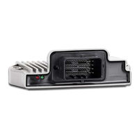
Bucher JXM-IO-E32 User Manual (55 pages)
Expansion module
Brand:
Bucher
| Category:
Control Unit
| Size: 0 MB
Table of Contents
Table of Contents
3
Introduction
5
Information on this Document
5
Typographical Conventions
5
Safety
6
General Information
6
Purpose
6
Intended Use
6
Usage Other than Intended
6
Warnings Used in this Document
7
Product Description
8
Design
8
Product Features
8
Fig. 1 Design
8
Diagnostic Capability Via Leds
9
Nameplate
10
Scope of Delivery
10
Fig. 2 Nameplate
10
Technical Specifications
11
Dimensions
11
Fig. 3 Dimension in MM
11
Mechanical Specifications
12
Electrical Properties
12
Tab. 1 Mechanical Specifications
12
Tab. 2 ECU Power Supply
12
Tab. 3 Ground Reference
12
Tab. 6 Irradiation ISO 11452
13
Tab. 7 Emission CISPR
13
Tab. 29 Parameter
13
Tab. 5 Pulses ISO 7637-2
13
Tab. 4 Environmental Conditions
13
EMI Values
13
Environmental Conditions
13
Outputs
14
Tab. 8 ESD en 61000-4-2
14
Tab. 9 Outputs AO_1
14
Tab. 10 Outputs VREF_10V
14
Tab. 11 Sensor Output VEXT_SEN
14
Inputs
15
Tab. 12 Analog Inputs AI_1
16
Tab. 13 High-Precision Analog Inputs AI_PREC
16
Tab. 14 Digital Inputs DI_1
17
Tab. 15 Configuration Inputs CFG1
17
Mechanical Installation
18
Tab. 16 Requirements for the Mounting Surface
19
Mounting Orientation
19
Requirements for Installation Location and Mounting Surface
19
Allowed Mounting Orientations
20
Fig. 4 Allowed Mounting Orientations
20
Forbidden Mounting Orientations
21
Fig. 5 Forbidden Mounting Orientation
21
Installing the Expansion Module
22
Fig. 6 Installation Drawing
22
Tab. 17 Mounting Hardware
22
Electrical Connection
23
Pin Assignment
24
MOLEX Connector
24
Fig. 7 MOLEX Connector - Pin Assignment
24
Tab. 18 MOLEX Mating Connector Specification
25
Identification and Configuration
26
Identification
26
Device Information
26
Tab. 19 Device Information
26
Tab. 21 Electronic Nameplate
27
Tab. 20 EDS Information
27
Electronic Data Sheet (EDS)
27
Tab. 22 Jeteasydownload Parameters
28
Operating System
28
OS Update Via Jeteasydownload
28
Concept and Control
30
Configuration Options of Connections
30
Fig. 8 Concept and Control
30
Parameterization
30
I/O Ports and SDO Map
31
Tab. 23 Supported Ports and Interfaces - Overview
31
Tab. 24 SDO Mappings of the I/O Ports
31
Tab. 25 Subindexes for Accessing Parameters, Values, and Statuses
31
Overview - I/O Interfaces
32
Tab. 27 Input Values
34
Tab. 26 Available Interfaces, Parameters, Values and Statuses
34
Parameters, Values and Statuses
34
Tab. 28 Output Values
35
Tab. 30 Status
36
Setting the Node ID
37
Tab. 31 Offset for Set Base Node ID
37
Diagnostic Information
38
Tab. 32 Diagnostic Information
38
Tab. 33 Status Information
38
Saving Settings Permanently and Resetting to Default Values
39
Tab. 34 Saving Settings to EEPROM
39
Tab. 35 Resetting the Settings to Their Default Values
39
System Parameters
40
Tab. 36 System Parameters
40
Tab. 37 Validity of a PDO
41
Tab. 38 RPDO Communication Parameters
41
RPDO Communication Parameters
41
Mapping of Process Data Objects (Pdos)
41
TPDO Communication Parameters
42
Mapping Tables
42
Tab. 39 TPDO Communication Parameters
42
Tab. 40 RPDO Mapping Table
42
Sending Interface Input Values Via TPDO
43
Tab. 41 TPDO Mapping Table
43
Tab. 42 Mapping Entry U32
43
Frequency Measurement at the Digital Inputs
44
NMT Commands
45
Troubleshooting
45
Tab. 43 Supported NMT Commands
45
Tab. 44 Byte Values of Emergency Objects
45
Tab. 45 Byte Values of the Error Memory
45
Tab. 47 Emergency Error Codes
46
Tab. 46 Subindexes of the Error Memory
46
Heartbeat
47
Tab. 48 Index of the Heartbeat Message
47
Tab. 49 Heartbeat Monitoring
47
Tab. 50 Heartbeat Monitoring - Example
47
Maintenance
48
Repairs
48
Storage and Shipment
48
Return and Disposal
49
Fig. 9 WEEE Icon - Crossed out Trash Can
49
10 Service
50
Technical Support
50
11 Spare Parts and Accessories
51
Accessories
51
Tab. 51 Accessories
51
List of Figures
52
List of Tables
53
Advertisement
Advertisement
Related Products
Bucher JXM-IO-E31
Bucher JTM-4G-WiFi
Bucher JX3-CNT
Bucher JX3-BN-EC
Bucher JM-3524
Bucher JM-3P22B
Bucher JM-3P10B
Bucher JI-FPC2015
Bucher JC-365MC
Bucher JM-D2000
Bucher Categories
Control Unit
Blower
Power Supply
Amplifier
Touch terminals
More Bucher Manuals
Login
Sign In
OR
Sign in with Facebook
Sign in with Google
Upload manual
Upload from disk
Upload from URL