Sign In
Upload
Manuals
Brands
Brooks Instrument Manuals
Controller
GF100 Series
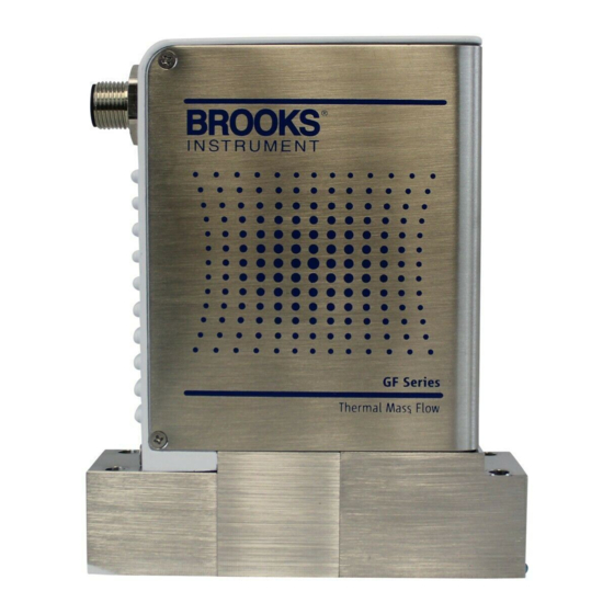
Brooks Instrument GF100 Series Manuals
Manuals and User Guides for Brooks Instrument GF100 Series. We have
2
Brooks Instrument GF100 Series manuals available for free PDF download: Installation & Operation Manual
Brooks Instrument GF100 Series Installation & Operation Manual (63 pages)
Metal Sealed, Thermal Mass Flow Controllers & Meters
Brand:
Brooks Instrument
| Category:
Controller
| Size: 7.58 MB
Table of Contents
Table of Contents
3
Section 1 General Information
5
GF100 Series High Performance Gas Flow Controller Analog and Digital
5
Product Support References
6
Notice and Caution Statements
6
Product Warranty
6
How to Order a GF100 Series Device
6
Industry Standard References
6
GF100 Series Gas Table
6
Glossary of Terms and Acronyms
6
How to Use this Manual
5
Introduction
5
Industry Standard References
7
Terms and Acronyms
8
Description
9
LCD Display
11
Specifications for GF100 Series Devices
12
Specifications for Standard GF100/GF120/GF125 Series
13
Specifications for Safe Delivery System (SDS) GF120 Series
14
Specifications for GF100/GF120/GF125 Series with Ethercat Communications
15
Specifications for GF135 Series
16
Specifications for GF101/GF121/GF126 Series
17
Specifications for GF101/GF121/GF126 Series with Ethercat Communications
18
Dimensions - GF100/GF120/GF125 Series
19
Dimensions - GF135, Devicenet
20
Dimensions - GF135, RS485
21
Dimensions - GF101/GF121/GF126
22
Section 2 Installation
24
General
24
Receipt of Equipment
24
Recommended Storage Practice
24
Return Shipment
24
Transit Precautions
25
Removal from Storage
25
Gas Connections
25
In-Line Filter
25
Mechanical Installation
25
Flow Controller Installation Arrangement
26
Dimensions - GF100/GF120/GF125, GF101/GF121/GF126 Series with Ethercat Communications19 2-1 Typical Gas Supply Arrangement with Non-PTI MFC
26
Typical Gas Supply Arrangement with PTI MFC
26
Purge the Gas Supply Line before GF100 Series Installation
27
Position and Mount the GF100 Series
28
GF100 Series Mounting Attitude Positions
28
GF100 Series Mounted to K1 Series Substrate Blocks
29
Mounting Screws Torque Pattern
29
K1 Series Fasteners
29
K1 Substrate Torque Data
29
Perform a Leak Test
30
Zeroing Setup Process
30
Zeroing the GF100 Series
30
Zeroing the GF100 Series Pressure Transducer from the LCD Display Panel
31
Display with PSI Reading
31
Display Reading Zero PSI
31
Zeroing GF100 Series Flow from LCD Display Panel
32
Performance Checks
32
Display Set to %FS
32
Flow Display Set to Zero
32
Introduction to the Multiflo TM Configurator
33
Using the Multiflo Configurator
33
Gas and Flow Ranges - Multiflo Configurable - N2 Equivalent
33
Multiflo Cable Adapter
34
USB-RS485 Converter (214F027AAA)
34
Diagnostic Port Locations
34
Electrical Connections
35
Devicenet Connections
35
GF100 Series Devicenet Connection
35
Analog/Rs485 Connections
36
GF100 Series with 9-Pin Analog Connector
36
Analog 9-Pin Connector (M)
36
Ethercat Connections
37
GF100 with Ethercat Communications, M8 Power Connector Location
37
M8 Power Connector Drawing
37
GF100 Series Electrical Interface Options
38
GF135 Inlet Valve Installation
39
GF135 Series Showing Inlet/Outlet Pneumatic Isolation Valve Lines
39
GF135 Commissioning
40
Section 3 Operation General
43
Theory of Operation for Flow Measurement
43
GF100 Series Operating Principles
45
Section 4 Maintenance & Troubleshooting Overview
46
Maintenance
46
Troubleshooting
48
Troubleshooting Checklist
48
Environmental Factors
48
GF100 Series Troubleshooting Guide
49
Section 5 Product Description Code Overview
53
GF100, GF120 & GF125 Series Product Description Code
54
GF100, GF120 & GF125 Series with Ethercat Communications Product Description Code
55
Model GF135 Product Description Code
56
GF101, GF121 & GF126 Series Product Description Code
57
GF101, GF121 & GF126 Series with Ethercat Communications Product Description Code
58
GF100 Series Gas Table - Codes 1-108, Bins SH40 to SH50
60
Appendix A: GF100 Series Gas Table Overview
61
GF100 Series Gas Table - Codes 109-875, Bins SH40 to SH50
61
GF100 Series Gas Table - Codes 878-5022, Bins SH40 to SH50
61
Appendix B: GF100 Series Patents Overview
62
GF100 Series Patents
62
Advertisement
Brooks Instrument GF100 Series Installation & Operation Manual (62 pages)
Mass Flow Controllers & Meters
Brand:
Brooks Instrument
| Category:
Measuring Instruments
| Size: 4.42 MB
Table of Contents
Table of Contents
3
Section 1 General Information
5
Introduction
5
How to Use this Manual
5
Product Support References
6
Notice and Caution Statements
6
Product Warranty
6
How to Order a GF100 Series Device
6
Industry Standard References
6
Glossary of Terms and Acronyms
6
Tables
7
Industry Standard References
7
Description
9
Figures
11
LCD Display
11
Specifications for Gf100/Gf120Xht/Gf101 Series Devices
12
Specifications for GF100/GF120/GF125 Series with Analog and DNET Communications
13
Specifications for GF100/GF120/GF125 Series with Ethercat Communications
15
Specifications for GF101/GF121/GF126 Series with Ethercat Communications
18
Specifications for Gf120Xht Series
19
Dimensions - GF100/GF120/GF125 Series
20
Dimensions - GF101/GF121/GF126 Series
21
Dimensions - GF100/GF120/GF125, GF101/GF121/GF126 Series with Ethercat Communications
22
Section 2 Installation
25
General
25
Receipt of Equipment
25
Recommended Storage Practice
25
Return Shipment
25
Transit Precautions
26
Removal from Storage
26
Gas Connections
26
In-Line Filter
26
Mechanical Installation
26
Flow Controller Installation Arrangement
27
Typical Gas Supply Arrangement with Non-PTI MFC
27
Typical Gas Supply Arrangement with PTI MFC
27
Purge the Gas Supply Line before GF100 Series Installation
28
GF100 Series Mounting Attitude Positions
29
Gf120Xht Series Mounting Attitude Positions
29
Position and Mount the Gf100/Gf120Xht/Gf101 Series
30
GF100 Series Mounted to K1 Series Substrate Blocks
31
Perform a Leak Test
32
Zeroing Setup Process
32
Zeroing the Gf100/Gf120Xht/Gf101 Series
32
Zeroing the GF125/GF126 Series Pressure Transducer from the LCD Display Panel
33
Zeroing Gf100/Gf120Xht/Gf101 Series Flow from LCD Display Panel
34
Performance Checks
34
Introduction to the Multiflo TM Configurator
35
Using the Multiflo TM Configurator
35
Diagnostic Port Locations
36
Electrical Connections
37
Devicenet Connections
37
Example of GF100 Series with a Devicenet Communication
37
Analog/Rs485 Connections
38
Example of GF100 Series with 9-Pin Analog Connector
38
Analog 9-Pin Connector, Alternate Pin-Out Options Available
38
Ethercat Connections
39
Gf120Xht Series Electrical Interface Options
41
Section 3 Operation
42
General
42
Theory of Operation for Flow Measurement
42
Section 4 Maintenance & Troubleshooting
44
Overview
44
Maintenance
44
Troubleshooting
46
Troubleshooting Checklist
46
Gf100/Gf120Xht/Gf101 Series Troubleshooting Guide
47
Section 5 Product Description Code
51
Overview
51
GF100, GF120 & GF125 Series Product Description Code
51
GF100 Series Ordering Instructions
59
Appendix A: GF100 Series Patents
61
Gf100/Gf120Xht/Gf101 Series Patents
61
Advertisement
Related Products
Brooks Instrument GF101
Brooks Instrument GF120
Brooks Instrument GF120XSD
Brooks Instrument GF120XSL
Brooks Instrument GF121
Brooks Instrument GF125
Brooks Instrument GF126
Brooks Instrument GP200 Series
Brooks Instrument GF120xHT Series
Brooks Instrument GT 1305
Brooks Instrument Categories
Measuring Instruments
Controller
Transducer
Power Supply
Control Unit
More Brooks Instrument Manuals
Login
Sign In
OR
Sign in with Facebook
Sign in with Google
Upload manual
Upload from disk
Upload from URL