Sign In
Upload
Manuals
Brands
Blue Giant Manuals
Trucks
EPJ-40
User Manuals: Blue Giant EPJ-40 Electric Pallet Jack
Manuals and User Guides for Blue Giant EPJ-40 Electric Pallet Jack. We have
1
Blue Giant EPJ-40 Electric Pallet Jack manual available for free PDF download: Owner's Manual
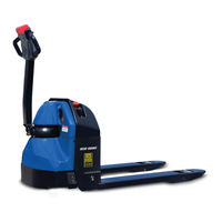
Blue Giant EPJ-40 Owner's Manual (124 pages)
ELECTRIC PALLET TRUCK
Brand:
Blue Giant
| Category:
Trucks
| Size: 5 MB
Table of Contents
Table of Contents
3
Figure 1-1 Name Plate
7
Figure 1-2. D40 Lift Truck
7
General Description
7
Introduction
7
Belly-Button Switch
8
Safety Features
8
D40 Lift Truck
9
Operation2-1
9
General
9
Operating Precautions
9
Before Operation
9
Name Plate
10
Figure 2-1Sample of Operator Check List
11
Belly-Button Switch
12
Driving and Stopping Procedures
12
Figure 2-2Forward/Reverse Control
12
Figure 2-3Pushbutton Switches
12
Figure 2-4Brake Actuation
12
General Control Operation
12
Backrest
13
Figure 2-5Belly-Button Switch
13
Guide Rails
13
Lift and Lower Controls
13
Loading and Unloading
13
Parking
13
Steering Arm Gas Spring
13
Planned Maintenance3-1
15
General
15
Monthly and Quarterly Checks
15
Battery Care
15
Safety Rules
16
Battery Care and Charging
16
Battery Cleaning
16
Maintenance Free Batteries
16
Charging Batteries
17
Figure 3-1Charging Battery
17
Batteries Replacement
18
Controller Board Removal
18
Cover Removal
18
Figure 3-2Cover Removal
18
Figure 3-3Controller Board Removal
18
Figure 3-4Lubrication Diagram
20
General
21
Controller Troubleshooting
24
Fault Detection
24
Figure 4-1Zapi Controller
24
Testing Truck Operation
24
Zapi Handset
24
Figure 4-2Zapi Handset
25
Settings and Adjustments
25
Figure 4-3Zapi Handset
29
Figure 4-4Throttle Regulation
30
Figure 4-5Zapi Handset
31
Lubrication
19
Lubrication Diagram
20
Figure 4-6Zapi Controller Connections
33
Zapi Controller
33
Steering Arm, Control Head and Compartment
37
Control Head
37
Control Head Removal
37
Figure 5-1Steering Arm
37
Figure 5-2Control Head
38
Control Head Installation
39
5-1.3. Cap Assembly Removal
39
5-1.4. Cap Assembly Installation
39
5-1.5. Speed Potentiometer Replacement
39
Figure 5-3Emergency Reverse Switch as
40
Figure 5-4Cap Assembly
41
Compartment Covers
42
Removal
42
Installation
42
Figure 5-5Compartment Cover
42
Steering Arm
43
Return Spring Replacement
43
Steering Arm Removal
43
Steering Arm Installation
43
Brake Servicing6-1
45
Brakes
45
Air Gap Adjustment
45
Figure 6-1Brake Assembly
45
Stopping Distance Adjustment
46
Brake Assembly Replacement
46
Transmission, Drive Wheel, Load Wheel7-1
47
Load Wheel
48
Removal
48
Repair
48
Load Wheel Installation
48
Figure 7-1Wheel Assembly
48
Drive Wheel
49
Transmission
49
Figure 7-2Transmission Motor, Brake
50
Elevation System Servicing8-1
51
General
51
Lift Linkage
51
Removal
51
Figure 8-1Frame
51
Repair
52
Installation
52
Figure 8-2Lift Linkage Assembly
52
Hydraulic System Servicing9-1
53
Lines and Fittings
53
Figure 9-1Hydraulic System
53
Hydraulic and Electrical Assembly
54
Removal
54
Installation
54
Hydraulic Pump, Motor, and Reser
54
Voir Assy9-2
54
Disassembly and Reassembly
54
Figure 9-2Pump & Motor Assy
55
Installation
56
Lift Cylinder
56
Electrical Components10-1
59
Electrical Control Panel
59
10-1.1.Maintenance
59
10-1.2.Cleaning
59
10-1.3.Controller Removal
59
10-1.4.Controller Installation
59
10-1.5.Charger Removal
59
10-1.6.Charger Installation
59
10-1.7.Emergency Disconnect Removal
60
10-1.8.Emergency Disconnect Installation
60
10-1.9.Contactor Removal
60
10-1.10.Contactor Installation
60
10-1.11.Fuse Removal
60
10-1.12.Fuse Installation
60
Figure 10-1Electrical Components
61
10-1.13.Cooling Fan Removal
62
10-1.14.Cooling Fan Installation
62
10-1.15.Buzzer Removal
62
10-1.16.Buzzer Installation
62
10-1.17.Key Switch Removal
62
10-1.18.Key Switch Installation
62
10-1.19.Battery Indicator Removal
62
10-1.20.Battery Indicator Installation
62
Figure 10-2Electrical Components
63
10-1.21.Lift Limit Switch Removal
64
10-1.22.Lift Limit Switch Installation
64
Figure 10-3Electric System
64
Deadman Switch
65
10-4.1.Replacement
65
Optional Equipment11-1
67
Illustrated Parts Breakdown12-1
69
Figure 12-1Steering Arm
70
Steering Arm
71
Figure 12-2Control Head
72
Cap Assembly
73
Control Head
75
Figure 12-3Cap Assembly
76
Figure 12-4 Emergency Reverse Switch Assembly
78
Emergency Reverse Switch Assembly
79
Figure 12-5Transmission Motor, Brake Mounting
80
Brake Assembly
81
Transmission Motor, Brake Mounting
81
Figure 12-6Transmission Transmission Used up to Serial # E2219364
82
Figure 12-7Transmission Used from Serial # E2219365
88
Figure 12-8Compartment Covers
90
Compartment Cover
91
Figure 12-9Load Backrest
92
Load Backrest
93
Figure 12-10Frame
94
Frame
95
Figure 12-11Lift Link Assembly
96
Load Wheel
97
Figure 12-12Load Wheel
98
Figure 12-13Caster
100
Caster
101
Figure 12-14Hydraulic System
102
Hydraulic System
103
Figure 12-15Pump & Motor Assy
104
Figure 12-16Lift Cylinder
106
Lift Cylinder
107
Figure 12-17Electrical System
108
Electrical System
109
Figure 12-18Motor Assembly
110
Motor Assembly
111
Figure 12-19Electrical Components
112
Figure 12-20Electrical Components (Sheet 2)
116
Electrical Components (Sheet 2)
117
Figure 12-21Wiring Harness
118
Wiring Harness
119
Figure 12-22Wiring Cables
120
Wiring Cables
121
Advertisement
Advertisement
Related Products
Blue Giant EPS-22
Blue Giant EPJ-30
Blue Giant EPJ-60R
Blue Giant EPJ-25
Blue Giant EPT-55
Blue Giant BG2-72
Blue Giant BGN-40
Blue Giant Categories
Lifting Systems
Forklifts
Trucks
Control Panel
Jacks
More Blue Giant Manuals
Login
Sign In
OR
Sign in with Facebook
Sign in with Google
Upload manual
Upload from disk
Upload from URL