Sign In
Upload
Manuals
Brands
Bio-Tek Manuals
Washer
ELx405
Bio-Tek ELx405 Manuals
Manuals and User Guides for Bio-Tek ELx405. We have
1
Bio-Tek ELx405 manual available for free PDF download: Operator's Manual
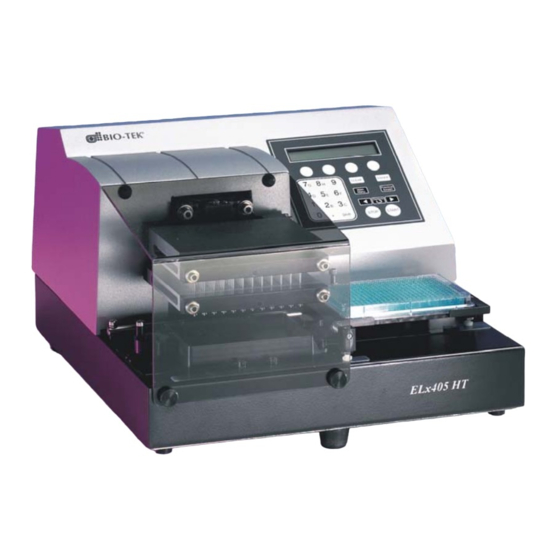
Bio-Tek ELx405 Operator's Manual (250 pages)
Microplate Washer
Brand:
Bio-Tek
| Category:
Washer
| Size: 3 MB
Table of Contents
Table of Contents
7
List of Figures
14
Contact Information
15
Customer Service and Sales
15
European Coordination Center
15
Service/Tac
15
Document Conventions
16
Revision History
17
Intended Use Statement
20
Quality Control
20
Repackaging and Shipping
20
Hazards
21
Hazards and Precautions
21
Warnings
21
Precautions
22
Directive 2002/96/EC: Waste Electrical and Electronic Equipment
24
Directive 73/23/EEC: Low Voltage (Safety)
24
Directive 89/336/Eec:electromagnetic Compatibility
24
Directive 98/79/EC: in Vitro Diagnostics (some Models)
25
Canadian Department of Communications Class a
26
Electromagnetic Interference and Susceptibility
26
Usa Fcc Class a
26
User Safety
26
Safety Symbols
27
Bio-Tek Instruments Warranty Policy
29
Hardware Warranty
29
Warranty
29
Registration Card
30
Registration Online
30
Chapter 1: Introduction
32
Introducing the Elx405
32
Elx405 Washer Variations
33
Compatibility with the Bio-Stack System
34
Figure 1: the Elx405™ Microplate Washer with the Bio-Stack
35
Hardware Features
36
Software Features
37
Package Contents
38
Optional Accessories
39
Specifications
40
Performance Specifications
41
Technical Support
42
Phone Support
43
Electronic Communication
43
Facsimile Support
43
Written Communication
43
Shipping Address
43
Applications Support
44
Phone Support
44
Electronic Communication
44
Chapter 2: Installation
46
Unpacking and Inspecting the Instrument
46
To Unpack the Washer and Its Accessories
46
Figure 2: Removing the Inner Shipping Box
47
Figure 3: Removing the Carrier and Other Accessories
47
Figure 4: Removing the End Caps
48
Figure 5: Manifold Shipping Bracket
48
Unpacking the Valve Module
49
Figure 6: Removing the Valve Module from the Shipping Container
50
Figure 7: Removing the Wire Holders, Supply Bottles, and Other Accessories
50
Removing the Manifold Shipping Bracket
51
Figure 8: Removing and Storing the Manifold Shipping Bracket
51
Setting up the Washer
52
Operating Environment
52
Installing the Microplate Carrier
52
Figure 9: Installing the Microplate Carrier for the Elx405 Model
53
Figure 10: Installing the Microplate Carrier for the Select, Select CW, and All HT Models
54
Figure 11: Installing the Microplate and Magnet Plate Carriers for the Magna Model
55
Connecting the Tubes and Bottles
56
Figure 15: Washer with External Valve Module
62
Attaching the Mist Shield
63
Figure 16: Attaching the Mist Shield
63
Connecting the Power Cord
64
Serial Port for Communication with Other Devices
64
Verifying Performance
65
Installation of the Washer for Operation with the Bio-Stack
66
Repackaging and Shipping
67
Before Repackaging the Instrument
68
Repackaging the Elx405 and Its Accessories
69
Repackaging the External Valve Module (if Equipped)
69
Chapter 3: Operation
72
Elx405 Front Panel
72
Figure 17: Elx405 Front Panel with LCD and Keypad
72
Keypad Description
73
Entering Program Names
74
System Startup
75
Main Menu
76
Programs
77
Operation with the Bio-Stack
78
General Usage Guidelines
79
Before Running any Program
79
Maintenance
80
Programming Considerations
81
Wash
82
Run Wash Program
82
Define Wash Program
83
Figure 18: Dispense and Aspirate Heights for the Elx405 and Magna Models
98
Figure 19: Dispense and Aspirate Heights for the Select, Select CW, and HT2/HTV2 Models with Dual/96 Manifold
99
Figure 20: Dispense and Aspirate Heights for the HT Model
100
Edit Wash Program
101
Copy Wash Program
101
Delete Wash Program
102
Prime
103
Run Prime Program
103
Define Prime Program
104
Recommended Prime and Low Flow Prime Volumes
106
Edit Prime Program
106
Copy Prime Program
107
Delete Prime Program
107
Default Prime Program: Prime_200
108
Default Prime Program: Prime_Cw
108
Dispense
109
Run Dispense Program
109
Define Dispense Program
110
Edit Dispense Program
111
Copy Dispense Program
111
Delete Dispense Program
112
Aspiration
113
Run Aspiration Program
113
Define Aspiration Program
114
Edit Aspiration Program
114
Copy Aspiration Program
115
Delete Aspiration Program
115
Soak
116
Define Soak Program
116
Edit Soak Program
116
Copy Soak Program
117
Delete Soak Program
117
Linking Programs
118
Run Link Program
118
Define Link Program
119
Delete Link Program
120
Setup Utilities
121
Settings (RS232)
121
Sensor System (SENSOR)
121
Adjust Utility (ADJUST)
122
Park Utility (PARK)
123
Bio-Stack Utilities (BIOSTACK)
123
Figure 21: Using the Adjust Utility
123
Delay after Dispense (DISP)
124
Plate Clearance Height (PLATE)
124
Vacuum Dissipation Delay (VACUUM)
124
Manifold Selection (MANIFOLD)
125
Elx405 Washer Menu Maps
126
Main Menu (DEFINE Function Path for Create and Edit)
127
Main Menu (DEFINE Function Path for Copy and Delete)
128
Main Menu (RUN Function Path)
129
Main Menu (MAINT, UTIL Function Path)
130
Chapter 4: Preventive Maintenance
131
Overview
132
Schedule
132
Recommended Maintenance Schedule
133
Required Materials
134
Warnings & Precautions
135
Maintenance Programs
136
Prime Programs
137
Rinse/Soak the Fluid Path
139
Daily Maintenance
139
Overnight/Multi-Day Maintenance
141
Clean Components
144
Periodic Maintenance
144
Figure 22: Position of the Transport Arm on the Plate Carrier
146
Figure 23: Removing the Screws and Washers from the Transport Arm
147
Figure 24: the Transport Arm Removed from the Carrier
147
Figure 25: Carrier and Manifold Placement in the Elx405 Model
150
Figure 26: Carrier and Manifold Placement in the Select, Select CW, and HT Models
151
Figure 27: Carrier and Manifold Placement in the Magna Model
152
Decontaminate the Washer
158
Decon Procedure for External Surfaces of the Instrument
159
Decon Procedure for Tubing and Manifold
160
Alternate Decontamination Procedure for Tubing and Manifold
162
Prepare for Storage or Shipment
164
Long_Shutdown
164
Storing the Washer
165
Replace Components
166
Replacing the O-Rings and Channel-End Seals
166
Figure 29: Replacing the Channel-End Seals
167
Chapter 5: Performance Verification/Qualification Tests
169
Overview
170
Verification Schedule
171
Installation Qualification (IQ)
172
Operational Qualification (OQ)
172
Performance Qualification (PQ)
173
System and Checksum Tests
174
System Self Test
174
Checksum Test
175
Liquid Tests
176
Evacuation Efficiency Test (Overview)
176
Dispense Precision Test (Overview)
176
Valve Module Test (Overview)
177
Which Tests to Perform
177
Materials
178
Evacuation Efficiency Test (96)
180
Dispense Precision Test (96)
183
Evacuation Efficiency Test (192)
187
Dispense Precision Test (192)
190
Worksheets
194
Appendix A: Troubleshooting
201
Overview
202
Troubleshooting Checklist
202
Troubleshooting Charts
203
Washer Start-Up
203
Figure 12: Rear Panel
203
Figure 13: Washer with Vacuum Pump and Waste Tubing Connections
203
Figure 14: Washer with Supply Tubing Connections (Without External Valve Module)
203
Figure 28: Cleaning the Fluid Inlet Filter
203
Fluid Aspiration
205
Fluid Delivery
208
Fluid Leakage
211
Microplate Carrier Movement
212
Washer Manifold Movement
212
Microplate Scratches
213
Appendix B: Error Codes
215
Error Codes
216
Bio-Stack Errors (Overview)
216
General Errors
217
Fatal Errors
230
Bio-Stack Errors
233
Appendix C: Chemical Compatibility
235
Components and Materials Composition
236
Appendix D: Default Programs
237
Default Programs
238
Appendix E: Changing the Manifolds
239
Changing Manifolds in HT Models with the 96-Tube Manifold
240
Figure 30: Storing the 96- or 192-Tube Dual Manifold in the Shipping Case
242
Index
243
Advertisement
Advertisement
Related Products
Bio-Tek ELx405 HT
Bio-tek ELx800
Bio-Tek Categories
Measuring Instruments
Laboratory Equipment
Washer
Card Reader
More Bio-Tek Manuals
Login
Sign In
OR
Sign in with Facebook
Sign in with Google
Upload manual
Upload from disk
Upload from URL