Sign In
Upload
Manuals
Brands
Biasi Manuals
Boiler
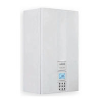
Inovia 25S ERP
User Manuals: Biasi Inovia 25S ERP Gas Boiler
Manuals and User Guides for Biasi Inovia 25S ERP Gas Boiler. We have
3
Biasi Inovia 25S ERP Gas Boiler manuals available for free PDF download: User Manual And Installation Instructions, Service Manual
BIASI Inovia 25S ERP User Manual And Installation Instructions (84 pages)
Wall hung, fanflue, roomsealed, high efficiency gas boiler
Brand:
BIASI
| Category:
Boiler
| Size: 10 MB
Table of Contents
Installation Instructions
1
Installing the Boiler
6
Table of Contents
7
1 Appliance Description
8
Overview
8
Isolation Valves
8
Control Panel
9
LCD General Features
9
2 Instructions for Use
13
Warnings
13
Refilling Procedure
13
Ignition
14
Circuit Temperature
15
Switching off
18
3 Useful Advice
20
Central Heating
20
Frost Protection
20
Condensate Drain
20
Periodic Maintenance
20
External Cleaning
21
Operational Faults
21
Displaying in INFO Mode
22
Remote Anomaly Code
23
Flue Probe
23
4 Technical Information
24
Overview
24
Main Diagram
25
Hydraulic Specifications
27
Expansion Vessel
27
Technical Data Inovia 25S ERP
28
5 General Requirements
31
Related Documents
31
Location of Appliance
31
Flue System
32
Gas Supply
33
Air Supply
34
Ventilation
34
Condensate Drain
34
Water Circulation (C.H.)
35
Water Treatment
36
Electrical Supply
36
6 Installation
37
Warnings
37
Precautions for Installation
37
Installing the Bracket
38
Overall Dimensions
39
Joints
39
Mounting the Boiler
39
Fitting the Flue System
40
Choice of Flue
40
Electric Connection
43
Connecting the Room Thermostat or Zone Valves
44
External Frost Protection
46
Connecting a System Boiler to a Cylinder
47
Installation of the External Temperature Probe
51
(Optional)
51
Electric Connection between the Boiler and the External Probe
51
Remote Electric Connection (Optional)
51
Example of Hydraulic Systems with Hydraulic
52
Separator
52
7 Commissioning
53
Warnings
53
Electrical Installation
53
Gas Supply Installation
53
Initial Filling of the System
53
Condensate Pipe and Traps
55
Checking the Gas Supply Pressure
55
Checking the Inlet Pressure
55
Lighting the Boiler
56
Checking the Ignition Device
57
Checking the Flue System
57
Checking the Condensate Drain Pipe
57
Instructing the User
58
8 Advanced Commissioning
59
Enabling Functioning of the External
59
Setting the K Coefficient of the External Temperature Probe
59
Setting the Pump Post-Circulation
61
Selecting the Reignition Frequency
63
Boiler Adjustment Record
65
9 Gas Conversion
67
Warnings
67
Operations and Gas Setting
67
10 Maintenance
69
Warnings
69
Programming the Maintenance Period
69
Dismantling the External Panels
70
Reassembly the External Panels
71
Emptying the C.H. System
71
Cleaning the Condensing Primary Exchanger
72
And the Burner
72
Check the Pressure of the Heating Expansion Vessel
74
Checking the Flue System
74
Combustion Analysis Check
74
Checking the Condensate Drain Pipe
75
Visual Inspection of Appliance
75
Checking the Gas Supply Pressure
75
Water Inhibitor Concentration
75
Setting the Boiler Flue Sweep Function
75
11 Benchmark Commissioning and Servicing Section
78
Gas Boiler System Commissioning Checklist
79
Service Record
80
Advertisement
Biasi Inovia 25S ERP User Manual And Installation Instructions (80 pages)
Wall hung, fanflue, roomsealed, high efficiency gas boiler
Brand:
Biasi
| Category:
Boiler
| Size: 9 MB
Table of Contents
Installation Instructions
1
Using the Boiler
3
Installing the Boiler
6
Table of Contents
7
1 Appliance Description
8
Overview
8
Isolation Valves
8
Controls Panel
8
LCD General Features
9
2 Instructions for Use
13
Warnings
13
Refilling Procedure
13
Ignition
14
C.h. Circuit Temperature
15
Extinguishing
19
3 Useful Advice
20
Central Heating
20
Frost Protection
20
Condensate Drain
20
Periodic Maintenance
20
External Cleaning
21
Operational Faults
21
Displaying in INFO Mode
22
Remote Anomaly Code
23
Flue Probe
23
4 Technical Information
24
Overview
24
Main Diagram
25
Hydraulic Specifications
27
Expansion Vessel
27
Technical Data Inovia 25S ERP
28
5 General Requirements
31
Related Documents
31
Location of Appliance
31
Flue System
32
Gas Supply
33
Air Supply
33
Ventilation
33
Condensate Drain
33
Water Circulation (C.h.)
34
Water Treatment
35
5.10 Electrical Supply
35
6 Installation
36
Warnings
36
Precautions for Installation
36
Installing the Bracket
37
Overall Dimensions
38
Joints
38
Mounting the Boiler
38
Fitting the Flue System
39
Choice of Flue
40
Electric Connection
43
Connecting the Room Thermostat or Zone Valves
45
6.11 External Frost Protection
47
Connecting a System Boiler to a Cylinder
47
Installation of the External Temperature Probe
51
(Optional)
51
Electric Connection between the Boiler and the External Probe
51
Remote Electric Connection (Optional)
51
Example of Hydraulic Plants with Hydraulic
52
Separator
52
7 Commissioning
53
Warnings
53
Electrical Installation
53
Gas Supply Installation
53
Initial Filling of the System
53
Condensate Pipe and Traps
55
Checking the Gas Supply Pressure
55
Checking the Inlet Pressure
55
Lighting the Boiler
56
Enabling Functioning of the External Temperature Probe by the Remote Control
57
Setting the K Coefficient of the External Temperature Probe
58
Setting the Pump Post-Circulation
60
Selecting the Reignition Frequency
62
7.13 Checking the Ignition Device
63
7.14 Checking the Flue System
63
Checking the Condensate Drain Pipe
64
7.16 Instructing the User
64
Adjustment of Useful C.h. Output
64
7.18 Setting Record
65
8 Gas Conversion
67
Warnings
67
Operations and Gas Setting
67
9 Maintenance
69
Warnings
69
Programming the Maintenance Period
69
Dismantling the External Panels
70
Reassembly the External Panels
71
Emptying the C.h. System
71
Cleaning the Condensing Primary Exchanger
72
And the Burner
72
Check the Pressure of the Heating Expansion Vessel
73
Checking the Flue Expulsion Pipe
74
Combustion Analysis Check
74
Checking the Condensate Drain Pipe
74
9.11 Visual Inspection of Appliance
74
Checking the Gas Supply Pressure
75
9.13 Water Inhibitor Concentration
75
Setting the Boiler Chimney Sweep Function
75
10 Benchmark Commissioning and Servicing Section
77
Gas Boiler System Commissioning Checklist
78
Service Record
79
Biasi Inovia 25S ERP Service Manual (52 pages)
G.C. Appl. No. 47-583-38, 47-583-39, 47-583-40, 41-583-30
Brand:
Biasi
| Category:
Boiler
| Size: 8 MB
Table of Contents
Table of Contents
3
Overall Information
4
Overall View
4
Hydraulic Diagram
4
General Access and Emptying Hydraulic Cir
5
Cuits
5
Nomenclature
5
Case Panels
5
Control Panel
6
Main Electronic P.C.b. Box
6
Emptying the Primary Circuit
7
Emptying the D.h.w. Circuit
7
Diagrams
8
Wiring Diagram Inovia 25C ERP - Inovia 30C ERP - Inovia 35C ERP
8
Wiring Diagram Inovia 25S ERP
9
Circuit Voltages
10
Fault Finding
11
Fault Finding
13
Display Diagnostic
13
Condensing Heat Exchanger
14
Function
14
Removal
14
Cleaning
15
D .H .W . Heat Exchanger
16
Function
16
Removal
16
Pump
17
Function
17
Removal Pump
17
Three Way Diverter Valve
18
Function
18
Checks
18
Removal of the Electric Actuator
18
Removal of the Three Way Diverter Valve
19
Removal of the Diverter Group
19
MAIN Electronic Control/Ignition P.C.b
20
Function
20
Selection and Adjustment Devices
20
Checking the Temperature
21
Setting the Boiler Control Function Modes
22
Checks
25
Removal of the Electronic Control P.C.b
25
Thermal Control in the
26
Thermal Control in the Mode
27
Mode
27
Control Panel Electronic P.C.b
28
Function
28
Normaly Information
28
Signal Displayed by Lcd
29
Info Modality
30
Function Modes Setting Modality
30
Removal of the Control Panel Electronic P.C.b
30
Removal of the Interface Electronic P.C.b
30
Gas Valve
32
Function
32
Description of the Parts - (Figure 11.2)
32
Adjustment
32
Checks
34
Removal of the Gas Valve
34
Primary Circuit Flow Switch
35
Function
35
Checks
35
Removal
35
Expansion Vessel and Pressure Gauge
36
Function
36
Checks
36
Removal of the Expansion Vessel
36
14 D .H .W . Flow Switch, Filter and Flow Limiter
37
Function
37
Description and Location of Parts - (Figure 14.2)
37
Removal of the Sensor
37
Checks
37
Removal Of The Flow Switch Group And D.h.w. Circuit Filter
38
Flow Limiter
38
Temperature Probe
39
Function
39
Checks
39
Removal of the C.h. Temperature Probes
39
Removal of the D.h.w. Temperature Probes
39
By-Pass Valve
41
Function
41
Removal
41
Fan and Air Box
42
Function
42
Removal of the Air Box and the Fan
42
Ignition, Detection Electrodes and Burner
43
Function
43
Removal of the Ignition and Detection Electrodes
43
Removal of the Burner
43
Removal of the Front Insulation Panel
44
Removal of the Rear Insulation
44
Checks
44
Ignition and Detection Electrodes
45
Safety Thermostat
46
Function
46
Checks
46
Removal
46
Flue Temperature Probe Ntc and Safety Ther
47
Mal Fuse
47
Function
47
Removal
47
Checks
47
Condensate Trap
49
Function
49
Check the Cleanness of the Trap
49
Removal
49
Short Spare Parts List
50
Advertisement
Advertisement
Related Products
Biasi Basica Cond 25S
Biasi Inovia 25C
Biasi Inovia 25C ERP
Biasi 25 CH
Biasi 25 PE
Biasi 24S
Biasi 28S
Biasi 24SR
Biasi KAPPA 27R
Biasi ADVANCE 24OV
Biasi Categories
Boiler
Heat Pump
Gas boiler
Water Heater
Heater
More Biasi Manuals
Login
Sign In
OR
Sign in with Facebook
Sign in with Google
Upload manual
Upload from disk
Upload from URL