Sign In
Upload
Manuals
Brands
Beckhoff Manuals
Control Unit
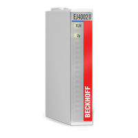
EJ4002
Beckhoff EJ4002 Manuals
Manuals and User Guides for Beckhoff EJ4002. We have
1
Beckhoff EJ4002 manual available for free PDF download: Documentation
Beckhoff EJ4002 Documentation (65 pages)
Analog Output Modules (12 Bit)
Brand:
Beckhoff
| Category:
Control Unit
| Size: 5 MB
Table of Contents
Table of Contents
3
1 Foreword
5
Product Overview Analog Output Modules
5
Notes on the Documentation
5
Safety Instructions
7
Intended Use
8
Signal Distribution Board
8
Documentation Issue Status
8
Guide through Documentation
8
Marking of Ethercat Plug-In Modules
9
Fig. 1 Order Identifier (A), Revision Number (B) and Serial Number (C) Using the Example of EJ1008
10
Fig. 2 Order Identifier (A), Revision Number (B) and Serial Number (C) Using the Example of EJ1008
11
Beckhoff Identification Code (BIC)
12
Fig. 3 BIC as Data Matrix Code (DMC, Code Scheme ECC200)
12
Certificates
14
Fig. 4 Marking for CE and UL Using EJ1008 as an Example
14
2 System Overview
15
Fig. 5 EJ System Sample
15
3 Product Overview
16
Ej4002, Ej4004, Ej4008
16
EJ4002, EJ4004, EJ4008 - Introduction
16
Fig. 6 EJ4002, EJ4004, EJ4008
16
EJ4002, EJ4004, EJ4008 - Technical Data
17
EJ4002 - Pinout
18
Fig. 7 EJ4002 - Pinout
18
EJ4004 - Pinout
19
Fig. 8 EJ4004 - Pinout
19
EJ4008 - Pinout
20
Fig. 9 EJ4008 - Pinout
20
Ej40Xx - Leds
21
Fig. 10 Ej40Xx - Leds
21
Ej4018, Ej4024
22
EJ4018, EJ4024 - Introduction
22
Fig. 11 EJ4018, EJ4024
22
EJ4018, EJ4024 - Technical Data
23
EJ4018 - Pinout
24
Fig. 12 EJ4018 - Pinout
24
EJ4024 - Pinout
25
Fig. 13 EJ4024 - Pinout
25
Ej40Xx - Leds
26
Fig. 14 Ej40Xx - Leds
26
4 Installation of EJ Modules
27
Power Supply for the Ethercat Plug-In Modules
27
Fig. 15 E-Bus Power Supply with EJ1100 or EJ1101-0022 + Ej940X
27
Fig. 16 PCB with Embedded PC, EK1110-0043 and Ejxxxx, Rear View EK1110-0043
28
Ejxxxx - Dimensions
29
Fig. 17 Ejxxxx - Dimensions
29
Fig. 18 Technical Drawings from Download Finder
29
Installation Positions and Minimum Distances
30
Minimum Distances for Ensuring Installability
30
Fig. 19 Mounting Distances EJ Module - PCB
30
Installation Positions
31
Fig. 20 Recommended Distances for Standard Installation Position
31
Fig. 21 Other Installation Positions
32
Codings
33
Color Coding
33
Fig. 22 EJ Modules Color Code; Sample: EJ1809
33
Mechanical Position Coding
34
Fig. 23 Mechanical Position Coding with Coding Pins (B1 and B2) and Coding Holes (A1 and A2)
34
Fig. 24 Pin Coding; Sample: Digital Input Modules
34
Installation on the Signal Distribution Board
35
Fig. 25 Installation of EJ Modules
35
Extension Options
37
Using Placeholder Modules for Unused Slots
37
Fig. 26 Sample: Exchanging Placeholder Modules and Assigning Reserve Slots
37
Linking with Ethercat Terminals and Ethercat Box Modules Via an Ethernet/Ethercat Connection
38
IPC Integration
39
Fig. 27 Example PCB with Embedded PC, EK1110-0043 and Ejxxxx, Rear View EK1110-0043
39
Fig. 28 Example for the Connection of a C6015 IPC to an EJ System
40
Disassembly of the Signal Distribution Board
41
Fig. 29 Disassembly of EJ Modules
41
5 Ethercat Basics
42
6 Commissioning
43
Note on Documentation for the El40Xx
43
Ej40Xx - Object Description and Parameterization
43
Restore Objects
44
Configuration Data
44
Output Data
45
Standard Objects
45
7 Appendix
51
Ethercat al Status Codes
51
Ej40Xx - Firmware Compatibility
51
Firmware Update El/Es/Em/Elm/Epxxxx
52
Device Description ESI File/Xml
53
Fig. 30 Device Identifier Consisting of Name EL3204-0000 and Revision -0016
53
Fig. 31 Scan the Subordinate Field by Right-Clicking on the Ethercat Device
54
Fig. 32 Configuration Is Identical
54
Fig. 33 Change Dialog
54
Fig. 34 EEPROM Update
55
Fig. 35 Selecting the New ESI
55
Firmware Explanation
56
Fig. 36 Display of EL3204 Firmware Version
56
Updating Controller Firmware *.Efw
57
Fig. 37 Firmware Update
57
FPGA Firmware *.Rbf
58
Fig. 38 FPGA Firmware Version Definition
59
Fig. 39 Context Menu Properties
59
Fig. 40 Dialog Advanced Settings
60
Simultaneous Updating of Several Ethercat Devices
62
Fig. 41 Multiple Selection and Firmware Update
62
Restoring the Delivery State
63
Fig. 42 Selecting the "Restore Default Parameters" PDO
63
Fig. 43 Entering a Restore Value in the Set Value Dialog
63
Support and Service
64
List of Illustrations
65
Advertisement
Advertisement
Related Products
Beckhoff EJ40 Series
Beckhoff EJ4004
Beckhoff EJ4008
Beckhoff EJ4018
Beckhoff EJ4024
Beckhoff TwinSAFE EJ19 Series
Beckhoff TwinSAFE EJ29 Series
Beckhoff TwinSAFE EJ1957
Beckhoff TwinSAFE EJ2918
Beckhoff EJ7211-0010
Beckhoff Categories
Touch terminals
Industrial PC
Control Unit
Industrial Equipment
Power Supply
More Beckhoff Manuals
Login
Sign In
OR
Sign in with Facebook
Sign in with Google
Upload manual
Upload from disk
Upload from URL