Sign In
Upload
Manuals
Brands
Beckhoff Manuals
Control Unit
C9900-M800
Beckhoff C9900-M800 Push Button Extension Manuals
Manuals and User Guides for Beckhoff C9900-M800 Push Button Extension. We have
2
Beckhoff C9900-M800 Push Button Extension manuals available for free PDF download: Manual
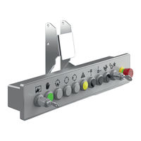
Beckhoff C9900-M800 Manual (40 pages)
Push Button Extension
Brand:
Beckhoff
| Category:
Control Unit
| Size: 7 MB
Table of Contents
Table of Contents
3
1 Notes on the Documentation
5
2 For Your Safety
6
Description of Safety Symbols
6
Intended Use
6
Fundamental Safety Instructions
7
Operator's Obligation to Exercise Diligence
7
3 Product Overview
8
Structure
9
Fig. 1 C9900-M800_Structure
9
Table 1 Key for C9900-M800 Structure
9
Interface Description
10
Power Supply
10
Fig. 2 C9900-M800_Voltage Sockets Pin Numbering
10
Table 2 Voltage Socket Pin Assignment
10
External Digital Outputs
11
Ethernet
11
Fig. 3 C9900-M800_Connection of Digital Outputs
11
Fig. 4 C9900-M800_Ethernet Interface Pin Numbering
11
Table 3 Connection of Digital Outputs Pin Assignment
11
Table 4 Ethernet Interface Pin Assignment
11
Switches and Push Buttons
12
Fig. 5 C9900-M800_Switches and Push Buttons
12
Table 5 Description of C9900-M800 Switches and Push Buttons
12
Name Plate
13
Connecting Cable
13
Fig. 6 C9900-M800_Address Selection Switch Sticker
13
Fig. 7 C9900-M800_Name Plate
13
Table 6 Key for C9900-M800 Name Plate
13
Table 7 Power Supply Connection Cable
14
Table 8 Ethernet Connection Cable
14
4 Commissioning
15
Transport and Storage
15
Mounting
16
Fig. 8 Cp32Xx_Mounting Arms
16
Table 9 Mounting Arm Ordering Options
16
Dimensions
17
Fig. 9 C9900-M800_Dimensions
17
Mounting Arm Installation
18
Fig. 10 C9900-M800_Mounting on the Mounting Arm
18
Connecting the Push Button Extension
19
Grounding of the Push Button Extension
19
Fig. 11 C9900-M800_Functional Earthing
19
Connecting Cables and Power Supply
20
Fig. 12 Cp32Xx_Wiring
20
Switching the Push Button Extension on and off
21
Commissioning Safety
22
Setting the Safety Addresses
22
Installing the GSDML File
22
Fig. 13 C9900-M800_Using the GSDML File
22
Process Image and Diagnostics
23
Fig. 14 C9900-M800_Device Overview
23
Fig. 15 C9900-M800_Process Image in Normal Operation
23
Table 10 Description of Switches and Push Buttons
24
Fig. 16 C9900-M800_Safety-Relevant Application
25
Fig. 17 C9900-M800_Error Message Example
26
Table 11 Overview of Module Faults
26
Table 12 Link Status Overview
26
Fig. 18: C9900-M800_Process Image, no Link at Port 1
27
Table 13 Error Indication Leds
27
Fig. 19 C9900-M800_Diagnostic Leds
28
5 Decommissioning
29
Disconnecting the Power Supply and Cables
29
Disassembly and Disposal
30
Fig. 20 C9900-M800_Dismounting from the Mounting Arm
30
6 Servicing and Maintenance
31
7 Troubleshooting
32
Table 14 Troubleshooting
32
8 Technical Data
33
Table 15 Technical Data
33
Table 16 Safety Parameters C9900-M800
33
Table 17 Safety Parameters Safety Card
33
Table 18 Safety-Related Parameters Emergency Stop, Key Switch, Yellow Push Button
34
9 Appendix
35
Service and Support
35
Approvals
36
List of Figures
37
Advertisement
Beckhoff C9900-M800 Manual (41 pages)
Push button extension
Brand:
Beckhoff
| Category:
Industrial Equipment
| Size: 7 MB
Table of Contents
Table of Contents
3
Notes on the Documentation
5
For Your Safety
6
Description of Safety Symbols
6
Intended Use
6
Fundamental Safety Instructions
7
Operator's Obligation to Exercise Diligence
7
Notes on Information Security
8
Product Overview
9
Table 1 Legend for C9900-M800 Structure
10
Fig. 1 Structure
10
Fig. 7 Name Plate
10
Structure
10
Interface Description
11
Power Supply
11
Fig. 2 Voltage Socket Pin Numbering
11
Table 2 Voltage Socket Pin Assignment
11
Table 3 Connection of Digital Outputs Pin Assignment
12
Table 4 Ethernet Interface Pin Assignment
12
Ethernet
12
Fig. 4 Ethernet Interface Pin Numbering
12
Fig. 3 Connection of Digital Outputs
12
External Digital Outputs
12
Switches and Push Buttons
13
Fig. 5 Switches and Push Buttons
13
Table 5 Description of C9900-M800 Switches and Push Buttons
13
Fig. 6 Address Selection Switch Sticker
14
Table 6 Legend for C9900-M800 Name Plate
15
Name Plate
15
Connecting Cable
16
Table 7 Power Supply Connection Cable
16
Table 8 Ethernet Connection Cable
16
Commissioning
17
Transport and Storage
17
Mounting
18
Fig. 8 Mounting Arms Cp32Xx
18
Table 9 Mounting Arm Ordering Options
18
Dimensions
19
Fig. 9 Dimensions
19
Mounting Arm Installation
20
Fig. 10 Mounting Arm Installation
20
Connecting the Push Button Extension
21
Grounding of the Push Button Extension
21
Fig. 11 Functional Earth
21
Connecting Cables and Power Supply
22
Fig. 12 Wiring Cp32Xx
22
Switching the Push Button Extension on and off
23
Fig. 13 Use of GSDML File
24
Setting the Safety Addresses
24
Installing the GSDML File
24
Commissioning Safety
24
Process Image and Diagnostics
25
Fig. 14 Device Overview
25
Fig. 15 Process Image in Normal Operation
25
Table 10 Description of Switches and Push Buttons
26
Fig. 16 Safety-Relevant Application
27
Table 12 Link Status Overview
28
Fig. 17 Example Error Message
28
Table 11 Overview of Module Faults
28
Fig. 18: Process Image, no Link to Port 1
29
Fig. 19 Diagnostic Leds
29
Table 13 Error Indication Leds
29
Decommissioning
31
Disconnecting the Power Supply and Cables
31
Disassembly and Disposal
32
Fig. 20 Dismounting from the Mounting Arm
32
Servicing and Maintenance
33
Troubleshooting
34
Table 14 Troubleshooting
34
Technical Data
35
Table 15 Technical Data
35
Appendix
36
Service and Support
36
Approvals
37
List of Figures
38
Advertisement
Related Products
Beckhoff C9900-G072
Beckhoff C9900-G073
Beckhoff C9900-M Series
Beckhoff C9900-M899
Beckhoff C9900-M993
Beckhoff C9900-M994
Beckhoff C9900-M995
Beckhoff C9900-M997
Beckhoff C9900-M900
Beckhoff C9900-M998
Beckhoff Categories
Touch terminals
Industrial PC
Control Unit
Industrial Equipment
Touch Panel
More Beckhoff Manuals
Login
Sign In
OR
Sign in with Facebook
Sign in with Google
Upload manual
Upload from disk
Upload from URL