Sign In
Upload
Manuals
Brands
Beckhoff Manuals
Industrial Electrical
C9900-G05 Series
Beckhoff C9900-G05 Series Manuals
Manuals and User Guides for Beckhoff C9900-G05 Series. We have
1
Beckhoff C9900-G05 Series manual available for free PDF download: Manual
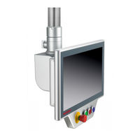
Beckhoff C9900-G05 Series Manual (38 pages)
Compact push-button extension
Brand:
Beckhoff
| Category:
Industrial Electrical
| Size: 3.82 MB
Table of Contents
Table of Contents
3
1 Notes on the Documentation
5
2 For Your Safety
6
Description of Safety Symbols
6
Intended Use
6
Fundamental Safety Instructions
7
Operator's Obligation to Exercise Diligence
7
3 Product Overview
8
Fig. 1 C9900-G05X Compact Push-Button Extension
8
C9900-G05X Ordering Options
9
Table 1 USB/ Directly Wired Versions
9
Table 2 Directly Wired Versions
10
Interface Description
12
Fig. 2 C9900-G05X Signal and Power Supply
12
Table 3 C9900-G050 and C9900-G052 Pin Assignment
12
Table 4 C9900-G054 and C9900-G056 Pin Assignment
12
Table 5 C9900-G051 and C9900-G053 Pin Assignment
13
Table 6 C9900-G055 and C9900-G057 Pin Assignment
13
Description of the Boards
14
Fig. 3 A918 Emergency Stop Board
14
Table 7 Connection Strip Assignment - A918 Emergency Stop Board
14
Fig. 4 A919 3-Button Board
15
Table 8 Assignment of Connection Strip - A919 Three-Button Board
15
Fig. 5 A920 4-Button Board
16
Table 9 Assignment of Connection Strip - A920 Four-Button Board
16
Fig. 6 A971 Emergency Stop Board
17
Fig. 7 A972 3-Button Board
17
Table 10 Connection Strip Assignment - A971 Emergency Stop Board
17
Fig. 8 A973 4-Button Board
18
Table 11 Assignment of Connection Strip - A972 Three-Button Board
18
Table 12 Assignment of Connection Strip - A974 Four-Button Board
18
Board Combination
19
Circuit Diagram - C9900-G050 and C9900-G052
20
Fig. 9 Circuit Diagram - C9900-G050 and C9900-G052
20
Circuit Diagram - C9900-G054 and C9900-G056
21
Fig. 10 Circuit Diagram - C9900-G054 and C9900-G056
21
Circuit Diagram - C9900-G051 and C9900-G053
22
Fig. 11 Circuit Diagram - C9900-G051 and C9900-G053
22
Circuit Diagram - C9900-G055 and C9900-G057
23
Fig. 12 Circuit Diagram - C9900-G055 and C9900-G057
23
Accessories
24
Signal and Power Supply - 19-Pin Round Connector
24
Fig. 13 19-Pin Round Connector
24
Table 13 Signal and Power Supply Cables
24
Table 14 Pin Assignment - 19-Pin Round Connector
24
Push-Button Caps and Inscription Labels
25
Fig. 14 Assembly of RAFI Labels and Push-Button Caps
25
Table 15 Optional Push-Button Caps and Inscription Labels
25
4 Commissioning
26
Transport and Unpacking
26
Commissioning in the Twincat System Manager
27
Fig. 15 Twincat XAE Project
27
Fig. 16 Twincat Scan Devices
27
Fig. 17 Twincat Select Device
28
Fig. 18 Twincat Scan Boxes
28
Fig. 19 Twincat Select Compatible Types
28
Table 16 List of Compatible Types
28
5 Decommissioning
29
6 Maintenance
30
7 Troubleshooting
31
Table 17 Troubleshooting
31
8 Technical Data
32
Table 18 Characteristics of the Respective Push-Button Extensions
32
Table 19 Characteristic Values Emergency Stop and Push-Buttons
32
9 Appendix
33
Service and Support
33
Approvals
34
List of Figures
35
Advertisement
Advertisement
Related Products
Beckhoff C9900-G050
Beckhoff C9900-G052
Beckhoff C9900-G054
Beckhoff C9900-G056
Beckhoff C9900-G051
Beckhoff C9900-G053
Beckhoff C9900-G055
Beckhoff C9900-G057
Beckhoff C9900-G028
Beckhoff C9900-G00 Series
Beckhoff Categories
Touch terminals
Industrial PC
Control Unit
Touch Panel
Power Supply
More Beckhoff Manuals
Login
Sign In
OR
Sign in with Facebook
Sign in with Google
Upload manual
Upload from disk
Upload from URL