
User Manuals: Becker RT6512 Remote-Controlled VHF Radio
Manuals and User Guides for Becker RT6512 Remote-Controlled VHF Radio. We have 3 Becker RT6512 Remote-Controlled VHF Radio manuals available for free PDF download: Installation And Operation Manual, Installation & Operation Manual

Becker RT6512 Installation And Operation Manual (64 pages)
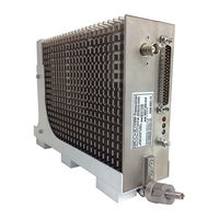
Remote-Controlled VHF-AM Transceiver
Brand: Becker
|
Category: Transceiver
|
Size: 1 MB
Table of Contents
Advertisement

Becker RT6512 Installation And Operation Manual (60 pages)
Remote-Controlled VHF-AM Transceiver
Brand: Becker
|
Category: Transceiver
|
Size: 1 MB
Table of Contents
Becker RT6512 Installation & Operation Manual (60 pages)
Remote-Controlled VHF-AM Transceiver
Brand: Becker
|
Category: Transceiver
|
Size: 1 MB
Table of Contents
Advertisement
Advertisement