Sign In
Upload
Manuals
Brands
Beck Manuals
Processor
IPC@CHIP SC2x3
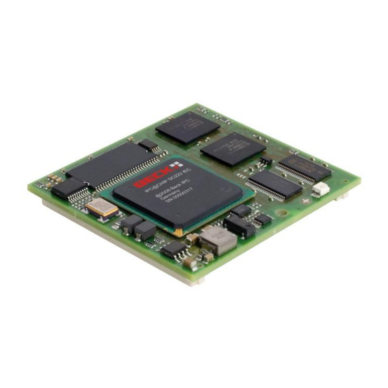
Beck IPC@CHIP SC2x3 Manuals
Manuals and User Guides for Beck IPC@CHIP SC2x3. We have
1
Beck IPC@CHIP SC2x3 manual available for free PDF download: Hardware Manual
Beck IPC@CHIP SC2x3 Hardware Manual (42 pages)
High Performance, 32-Bit Embedded Processor Computer on Module (CoM) with Flash, RAM, Watchdog
Brand:
Beck
| Category:
Processor
| Size: 1 MB
Table of Contents
Table of Contents
3
1 Overview
6
2 Features
7
3 Block Diagram
8
Figure 3-1: Block Diagram
8
4 Pin Description
9
Pin Configuration
9
Figure 4-1: Pin Configuration Looking through Top of Package
9
Address-/Data Bus
10
Local Plus Bus
11
ATA Interface
11
Table 4-1: Pin Description of Local Plus Bus Control Signals
11
Table 4-2: Pin Description of ATA Control Signals
11
USB1 - UART4+5 Interface
12
Psc1 - Uart1
13
Table 4-3: Pin Description of USB1 - UART4+5 Interface
13
Table 4-4: Pin Description of Programmable Serial Controller 1
13
Psc2 - Uart2 + Can
14
Table 4-5: Pin Description of Programmable Serial Controller 2
14
Psc3 - Uart3/Spi
15
Table 4-6: Pin Description of Programmable Serial Controller 3
16
Psc6 - Uart6
17
I²C Bus
17
Table 4-7: Pin Description of Programmable Serial Controller 6
17
Table 4-8: Pin Description of I²C Bus
17
MII Interface
18
Timers
18
Reset Signals
18
Table 4-9: Pin Description of MII
18
Table 4-10: Pin Description of Timers
18
Table 4-11: Pin Description of Reset Signals
18
COP/JTAG-Interface
19
Interrupts
19
Table 4-12: Pin Description of COP/JTAG-Interface
19
Power
20
Table 4-13: Pin Description of Power Pins
21
Programmable I/O Pins
22
Table 4-14: List of PIO Sharing Designations
22
5 Mutal Exclusive Functions
23
Mutal Exclusive Functions for USB1
23
Mutal Exclusive Functions for PSC1
23
Mutal Exclusive Functions for PSC2
23
Mutal Exclusive Functions for PSC3
24
Mutal Exclusive Functions for PSC6
24
Mutal Exclusive Functions for I2C
24
Mutal Exclusive Functions for TIMER
24
Mutal Exclusive Functions for Local Plus Bus
24
6 Functional Description
25
Local Plus Bus
25
Features
25
Interface
25
External Local Plus Bus Signals
26
Local Plus Bus Address / Data Pin Assignments
27
Programmable Serial Controllers
28
Uarts
28
Usage of PIO0
29
Figure 6-1: Internal Block Diagram of PIO0..PIO3 and UART1
29
I²C
30
Usb
31
Spi
31
Can
32
Table 6-1: Provided CAN Baud Rates
32
Timers
33
MII Interface
33
Reset
33
7 System Interrupts
34
Watchdog
34
8 Characteristics
35
Absolute Maximum Ratings
35
Recommended Operating Ranges
35
Voltage and Temperature
35
Supply Current
35
Table 8-1: Absolute Maximum Ratings
35
Table 8-2: Recommended Operating Ranges
35
Table 8-3: Supply Current
35
Inputs
36
Outputs
36
Table 8-4: Inputs
36
Table 8-5: Outputs
36
AC Characteristics
37
Muxed Mode
37
Figure 8-1: Timing Diagram - Muxed Mode
37
Non-Muxed Mode
38
Figure 8-2: Timing Diagram-Muxed Mode
38
Figure 8-3: Timing Diagram-Non-Muxed Mode
39
9 Package Information
40
Dimensions
40
Sc2X3 Connector
40
Figure 9-1: Package Dimensions. Top View through the Conductor Board
40
10 Custom Series Programming of Sc2X3
41
11 History
42
Advertisement
Advertisement
Related Products
Beck IPC@CHIP - SC12
Beck IPC@CHIP SC01
Beck IPC@CHIP SC02
Beck IPC@CHIP SC11
Beck IPC SC123-LF
Beck IPC SC123-IEC
Beck IPC SC123-IEC-LF
Beck IPC SC143-LF
Beck IPC SC143-IEC
Beck IPC SC143-IEC-LF
Beck Categories
Controller
Transducer
Industrial Equipment
Switch
Network Hardware
More Beck Manuals
Login
Sign In
OR
Sign in with Facebook
Sign in with Google
Upload manual
Upload from disk
Upload from URL