Table of Contents
Advertisement
Quick Links
IPC@CHIP SC2x3
Hardware Manual V1.02 [01.03.09]
©2000-2009 BECK IPC GmbH
Hardware Manual
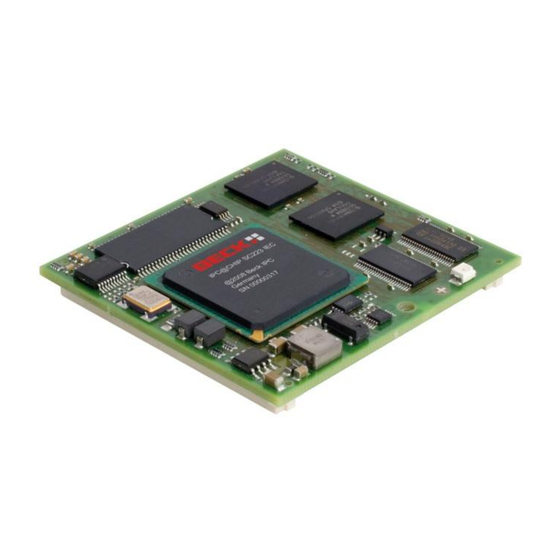
IPC@CHIP Embedded Controller Family
SC2x3
MPC5200
High Performance, 32-Bit Embedded Processor
Computer on Module (CoM) with Flash, RAM, Watchdog
Order No. IPC@CHIP
Embedded Controller SC243:
Embedded Controller SC243-IEC:
563963
Page 1
Advertisement
Table of Contents

Summary of Contents for Beck IPC@CHIP SC2x3
- Page 1 Hardware Manual V1.02 [01.03.09] Hardware Manual IPC@CHIP Embedded Controller Family SC2x3 MPC5200 High Performance, 32-Bit Embedded Processor Computer on Module (CoM) with Flash, RAM, Watchdog Order No. IPC@CHIP Embedded Controller SC243: 563963 Embedded Controller SC243-IEC: ©2000-2009 BECK IPC GmbH Page 1...
- Page 2 IPC@CHIP SC2x3 Hardware Manual V1.02 [01.03.09] Copyright & Trademark IPC@CHIP® is a registered trademark of Beck IPC. Ethernet is a registered trademark of Xerox Corporation. All other product names, company names, logos or other designations mentioned herein are trademarks of their respective owners.
-
Page 3: Table Of Contents
Usage of PIO0..PIO3 in consideration of UART1 (Bootloader interface) ..........29 6.2.3 I²C ................................30 6.2.4 USB ............................... 31 6.2.5 SPI ................................. 31 6.2.6 CAN ............................... 32 Timers ............................33 MII Interface ..........................33 Reset ............................33 ©2000-2009 BECK IPC GmbH Page 3... - Page 4 AC Characteristics ........................37 8.3.1 Muxed Mode ............................37 8.3.2 Non-Muxed Mode ..........................38 Package Information ....................40 Dimensions ..........................40 SC2x3 Connector ........................40 Custom series programming of SC2x3 ..............41 History ........................42 ©2000-2009 BECK IPC GmbH Page 4...
- Page 5 Table 6-1: Provided CAN baud rates ..........................32 Table 8-1: Absolute Maximum Ratings .......................... 35 Table 8-2: Recommended Operating Ranges ....................... 35 Table 8-3: Supply Current ............................. 35 Table 8-4: Inputs ................................36 Table 8-5: Outputs ................................. 36 ©2000-2009 BECK IPC GmbH Page 5...
-
Page 6: Overview
– ideal for fast data communication or complex control tasks for example in the field of motion control. As an option it can also be used in combination with an IEC61131-3 CoDeSys Run Time System. IPC@CHIP FLASH CoDeSys license included SC243 64 MByte 32 MByte SC243-IEC 64 MByte 32 MByte ©2000-2009 BECK IPC GmbH Page 6... -
Page 7: Features
Linear DC/DC Converter on the Module (3.3V on1.8V) 1,5V / 1,8V / 3,3V Supervisory Circuit Watchdog and power-on Reset Logic GPIOs 40 Programmable Input/Output (PIO) Pins Dimension 56 mm x 60 mm 240 Pin Board-to-Board connector system ©2000-2009 BECK IPC GmbH Page 7... -
Page 8: Block Diagram
JTAG IP Bus Memory C Bus Controller SDRA Flash Contr SRAM oller 10/100 I²C CAN 2.0 PSC1 PSC2 PSC3 PSC4 PSC5 PSC6 BaseT (two) J1850 (two) LM75 E²PROM V24 Transceiver Figure 3-1: Block Diagram ©2000-2009 BECK IPC GmbH Page 8... -
Page 9: Pin Description
IPC@CHIP SC2x3 Hardware Manual V1.02 [01.03.09] Pin Description 4.1 Pin Configuration Figure 4-1: Pin Configuration Looking through Top of Package ©2000-2009 BECK IPC GmbH Page 9... -
Page 10: Address-/Data Bus
31=msb). GPIO7 I/O[8mA] Transfer Size 1 indicates the size of the transaction in TSIZ[1] non-muxed mode or PIO31. PIO31 TEST_SEL_1 OUT[8mA] Transfer Size 2 indicates the size of the transaction in TSIZ[2] non-muxed mode. ©2000-2009 BECK IPC GmbH Page 10... -
Page 11: Local Plus Bus
ATA I/O Channel Ready (Active High with internal 10kOhm pullup) This pin is used to extend ATA bus accesses ATA DMA Request (Active High with internal 10kOhm ATA_DRQ pulldown) Table 4-2: Pin Description of ATA control signals ©2000-2009 BECK IPC GmbH Page 11... -
Page 12: Usb1 - Uart4+5 Interface
0=low speed or as PIO26. Ready to Send 5 Out RTS5 OUT[4mA] This pin provides the Ready to Send output for serial port 5. It provides the handshaking output for serial port 5. ©2000-2009 BECK IPC GmbH Page 12... -
Page 13: Psc1 - Uart1
DCD1 In the enhanced UART mode this signal must be assert during the data transmission. PIO4 I/O[4mA] This pin can slo be used as PIO4. Table 4-4: Pin Description of Programmable Serial Controller 1 ©2000-2009 BECK IPC GmbH Page 13... -
Page 14: Psc2 - Uart2 + Can
Data Carrier Detect 2 Input In the enhanced UART mode this signal must be assert during the data transmission. PIO9 I/O[4mA] This pin can also be used as PIO9. Table 4-5: Pin Description of Programmable Serial Controller 2 ©2000-2009 BECK IPC GmbH Page 14... -
Page 15: Psc3 - Uart3/Spi
This pin is used to detect single ended zero, error conditions, and interconnected speed. LP_CS6# OUT[8mA] Local Plus Bus Chip Select shared with PSC3 PIO14 I/O[8mA] This pin can also be used as PIO14. ©2000-2009 BECK IPC GmbH Page 15... -
Page 16: Table 4-6: Pin Description Of Programmable Serial Controller 3
This pin can also be used as PIO18. OUT[4mA] SPI Serial Clock USB2_OVRCNT USB 2 Overcurrent Detection PIO19 I/O[4mA] This pin can also be used as PIO19. Table 4-6: Pin Description of Programmable Serial Controller 3 ©2000-2009 BECK IPC GmbH Page 16... -
Page 17: Psc6 - Uart6
This pin can be used with the I²C block as the I2CCLK. I²C bus 2 Data (Schmitt Input with internal 10kOhm I2CDTA2 I/O[4mA] pullup) This pin can be used with the I²C block as the I2CDTA. Table 4-8: Pin Description of I²C Bus ©2000-2009 BECK IPC GmbH Page 17... -
Page 18: Mii Interface
Hardware Reset (Active Low, Schmitt Trigger Input with internal 10kOhm pullup) SRESET# IN/OUT [8mA] Software Reset (Active Low, Schmitt Trigger Input with internal 10kOhm pullup) Power On Reset (Active Low) PORRESET# OUT [4mA] Table 4-11: Pin Description of Reset signals ©2000-2009 BECK IPC GmbH Page 18... -
Page 19: Cop/Jtag-Interface
Interrupt 2 (Active High with internal 100kOhm pulldown) This pin is the external interrupt 0 request. Interrupt 3 (Active High with internal 100kOhm pulldown) IRQ3 This pin is the external interrupt 0 request. Table 4-13: Pin Description of Interrupts ©2000-2009 BECK IPC GmbH Page 19... -
Page 20: Power
Power I/O: +3.3 volt power supply Power I/O: +3.3 volt power supply Power I/O: +3.3 volt power supply Power VSS Power VSS Power VSS Power VSS Power VSS Power VSS Power VSS Power VSS Power VSS ©2000-2009 BECK IPC GmbH Page 20... -
Page 21: Table 4-13: Pin Description Of Power Pins
IPC@CHIP SC2x3 Hardware Manual V1.02 [01.03.09] Pin Name Type Description Power VSS Power VSS Power VSS Power VSS Power VSS Power VSS Power VSS Table 4-14: Pin Description of Power Pins ©2000-2009 BECK IPC GmbH Page 21... -
Page 22: Programmable I/O Pins
USB1_PRTPWR USB1 USB1_SPEED USB1 USB1_SUSPEND USB1 USB1_OVRCNT USB1 I2CCLK1 I2CDTA1 GPIO7 TIMER0 TIMER TIMER1 TIMER TIMER2 TIMER TIMER3 TIMER TIMER4 TIMER TIMER5 TIMER TIMER6 TIMER TIMER7 TIMER Table 4-15: List of PIO sharing designations ©2000-2009 BECK IPC GmbH Page 22... -
Page 23: Mutal Exclusive Functions
5.3 Mutal Exclusive Functions for PSC2 Function PSC 2 Nr. UART2 UART2e CODEC CAN1/2 PIO5 CODEC2_TXD CAN1TXD PIO6 CODEC2_RXD CAN1RXD PIO7 PIO7 CAN2TXD PIO8 CODEC2_CLK CAN2RXD PIO9 PIO9 CODEC2_FRAME PIO9 Table 5-3: Mutal Exclusive Functions for PSC2 ©2000-2009 BECK IPC GmbH Page 23... -
Page 24: Mutal Exclusive Functions For Psc3
Each timer (TIMER1-7) can be configured separately as timer or as PIO, inpependent from each other. 5.8 Mutal Exclusive Functions for Local Plus Bus Function PIO31 GPIO7/TSIZ[1]* Table 5-7: Mutal Exclusive Functions for I2C *GPIO7/TSIZ[1] is used to indicate the Transfer Size 1, see chapter4.2 Address-/Data Bus ©2000-2009 BECK IPC GmbH Page 24... -
Page 25: Functional Description
ALE (Address Latch Enable) ACK (Acknowledge) TS (Transfer Start) OE (Output Enable) TSIZ bits (Transfer Size) Bank Select bits Reference clock PCI_CLOCK The reference clock PCI_CLOCK is always running, even if the PCI Controller is disabled. ©2000-2009 BECK IPC GmbH Page 25... -
Page 26: External Local Plus Bus Signals
TSIZ bits are available in non-muxed modes on GPIO7 and TEST_SEL_1 pins. The MUXed Mode provides 3 bits TSIZ[0:2], which are available on EX_AD[30:28]. LP_ALE# Address Latch Enable Table 6-1: External Local Plus Bus Signals ©2000-2009 BECK IPC GmbH Page 26... -
Page 27: Local Plus Bus Address / Data Pin Assignments
EXT_AD[23] EXT_AD[22] EXT_AD[21] EXT_AD[20] EXT_AD[19] EXT_AD[18] EXT_AD[17] EXT_AD[16] EXT_AD[15] EXT_AD[14] EXT_AD[13] EXT_AD[12] EXT_AD[11] EXT_AD[10] EXT_AD[9] EXT_AD[8] EXT_AD[7] EXT_AD[6] EXT_AD[5] EXT_AD[4] EXT_AD[3] EXT_AD[2] EXT_AD[1] EXT_AD[0] Table 6-2: Local Plus Bus Address / Data Pin Assignments ©2000-2009 BECK IPC GmbH Page 27... -
Page 28: Programmable Serial Controllers
Hardware handshaking with the following selectable control signals: Clear-to-send (CTS) Ready-to-send (RTS) Data Carrier Detect (DCD) Separate maskable interrupts for each port Independent baud rate generators Maximum baud rate of 4.125 MBits/s Double-buffered transmit and receive ©2000-2009 BECK IPC GmbH Page 28... -
Page 29: Usage Of Pio0
This has to be considered, if PIO0..PIO3 is used. The following figure shows a block diagram of the internal schematic of the SC2x3. UART1 TXD/PIO0 RXD/PIO1 Transceiver RTS/PIO2 CTS/PIO3 PIO0 PIO1 PIO2 PIO3 Figure 6-1: Internal block diagram of PIO0..PIO3 and UART1 ©2000-2009 BECK IPC GmbH Page 29... -
Page 30: I²C
Bus busy detection more than 100 kHz operation Programmable Glitch Filter Note: On the I2C2 bus interface there are some internal devices present. So the following addresses can not be used externally: 0xA0, 0x90. ©2000-2009 BECK IPC GmbH Page 30... -
Page 31: Usb
The clock polarity, clock phase, SS (Slave Select) polarity, clock frequency in master mode, and the number of bits to be transferred are software programmable up to 66MHz. SPI supports multiple slaves on a single 3-wire bus by using separate Slave Select signals to enable the desired slave. ©2000-2009 BECK IPC GmbH Page 31... -
Page 32: Can
8-bit filters Programmable loop back mode supports self-test operation Programmable listen-only mode for monitoring of CAN bus Separate signalling and interrupt capabilities for all CAN receiver and transmitter error states (Warning, Error Passive, Bus-Off) ©2000-2009 BECK IPC GmbH Page 32... -
Page 33: Timers
The soft reset is a bidrectional signal with a Schmitt-Trigger input and open drain pullup including an internal resistor. It can be asserted by an external source or it can be asserted by the internal reset logic of the SC2x3. ©2000-2009 BECK IPC GmbH Page 33... -
Page 34: System Interrupts
800 ms. The mode can be set to trigger the watchdog by the user program or by the CHIP-RTOS (default). In CHIP-RTOS mode, the CHIP-RTOS performs the watchdog strobing provided that the system's timer interrupt is allowed to execute. Beware that excessive interrupt masking periods can lead to system resets. ©2000-2009 BECK IPC GmbH Page 34... -
Page 35: Characteristics
Note: Exposure to conditions beyond those listed here may adversely affect the lifetime and reliability of the device. Parameter Unit Supply Voltage (V 3.3 ±5% Operating Temperature -40..+85°C °C Table 8-2: Recommended Operating Ranges 8.2.2 Supply Current Parameter Unit Current into V @3,3V Table 8-3: Supply Current ©2000-2009 BECK IPC GmbH Page 35... -
Page 36: Inputs
High level output current @VOH 2.4V [4mA] High level output current @VOH 2.4V [8mA] High level output current @VOH 2.4V [16mA] Table 8-5: Outputs Note: [..mA] describes the driver category. E. g. [4mA] can source 4mA. ©2000-2009 BECK IPC GmbH Page 36... -
Page 37: Ac Characteristics
IPC@CHIP SC2x3 Hardware Manual V1.02 [01.03.09] 8.3 AC Characteristics Rastereinstellungen: 8.3.1 Muxed Mode Abstand horizontal: 0,15 Abstand vertikal: 0,3 1 Kästchen=0,5ns ? Figure 8-1: Timing Diagram – MUXed Mode ©2000-2009 BECK IPC GmbH Page 37... -
Page 38: Non-Muxed Mode
IPC@CHIP SC2x3 Hardware Manual V1.02 [01.03.09] Figure 8-2: Timing Diagram–MUXed Mode 8.3.2 Non-Muxed Mode ©2000-2009 BECK IPC GmbH Page 38... -
Page 39: Figure 8-3: Timing Diagram-Non-Muxed Mode
IPC@CHIP SC2x3 Hardware Manual V1.02 [01.03.09] Figure 8-3: Timing Diagram–Non-MUXed Mode ©2000-2009 BECK IPC GmbH Page 39... -
Page 40: Package Information
9.1 Dimensions Figure 9-1: Package Dimensions. Top view through the conductor board. 9.2 SC2x3 Connector Board-to-Board-connection via a 120-pole connector with 0.8-mm spacing. Manufacturer: Component: 5179031-5 Base board connectors are available in different heights. ©2000-2009 BECK IPC GmbH Page 40... -
Page 41: Custom Series Programming Of Sc2X3
This can be used to remote chiptool from other applications to program SC2x3 in series with high quantities. Chiptool also can program up to eight IPC@CHIPs parallel by using a PC with eight serial RS232 ports. See chiptool help file for more information. ©2000-2009 BECK IPC GmbH Page 41... -
Page 42: History
GmbH. The information in this document is subject to change Right to make changes — BECK IPC GmbH reserves the right without notice. Devices sold by BECK IPC GmbH. Are covered to make changes, without notice, in the products, including...
Need help?
Do you have a question about the IPC@CHIP SC2x3 and is the answer not in the manual?
Questions and answers