
Subscribe to Our Youtube Channel
Related Manuals for Basler DECS-100


Summary of Contents for Basler DECS-100
- Page 1 INSTRUCTION MANUAL DIGITAL EXCITATION CONTROL SYSTEM DECS-100 Publication: 9287500991 Revision: K 05/11...
- Page 3 DECS-100. NOTE Be sure that the DECS-100 is hard-wired to earth ground with no smaller than 12 AWG copp er wire atta ched to the grou nd termin al o n the rea r of the unit ca se.
- Page 4 May 2011 CONFIDENTIAL INFORMATION of Basler Electric, Highland Illinois, USA. It is loaned for confidential use, subject to return on request, and with the mutual understanding that it will not be used in any manner detrimental to the interest of Basler Electric.
- Page 5 REVISION HISTORY The following information provides a historical summary of the changes made to the DECS-100 hardware, firmware, and software. The corresponding revisions made to this instruction manual (9287500991) are also summarized. Revisions are listed in chronological order. Hardware Version and Date...
- Page 6 1 to 300 seconds throughout manual • Corrected figure number references in Sections 5 and 6 E, 03/04 • Added Operating Power Considerations During DECS-100 Programming Installation, Preliminary Setup Section 4, • Added caution box regarding application of operating power during DECS- BESTCOMS for Windows®...
- Page 7 • Revised voltage matching description to cover Maintain and Revert modes • Corrected the hole drilling diameter shown in Figure 4-2 • Added illustration/description for using the ICRM-7 with the DECS-100 BESTCOMS Software for the Palm® OS Platform • Removed Section 6,...
- Page 8 This page intentionally left blank. DECS-100 Introduction 9287500991 Rev K...
- Page 9 Section 1 General Information ....................1-1 Section 2 Human-Machine Interface ..................2-1 Section 3 Functional Description ....................3-1 Section 4 Installation ......................... 4-1 Section 5 BESTCOMS Software ....................5-1 Section 6 Maintenance and Troubleshooting................6-1 9287500991 Rev K DECS-100 Introduction...
- Page 10 This page intentionally left blank. viii DECS-100 Introduction 9287500991 Rev K...
-
Page 11: Table Of Contents
Metering (BESTCOMS) ........................1-5 Environment ............................1-6 Type Tests ............................1-6 Physical .............................. 1-6 Agency Recognition ........................... 1-6 CE Compliance ..........................1-6 Figures Figure 1-1. DECS-100 Style Chart ......................1-1 Figure 1-2. Typical V/Hz Curves ........................ 1-4 9287500991 Rev K DECS-100 General Information... - Page 12 This page intentionally left blank. DECS-100 General Information 9287500991 Rev K...
-
Page 13: Section 1 • General Information
The model number, together with the style number, describe the options included in a specific device, and appear on a label affixed to the rear panel. Upon receipt of a DECS-100, be sure to check the style number against the requisition and the packing list to ensure that they agree. -
Page 14: Specifications
Style Number Example For example, a DECS-100 with a style number of A15 would have the following characteristics and operating features. A ------- No var or power factor control 1 -------- Voltage matching 5 -------- 5 ampere current sensing SPECIFICATIONS DECS-100 specifications and qualifications are listed in the following paragraphs. -
Page 15: Accessory Input
Baud: 4800 Data Bits: Parity: None Stop Bit: Contact Input Circuits Type: Dry contacts Interrogation Voltage: 13 Vdc (supplied by DECS-100) Terminal Assignments for Standard Functions Raise: 6U, 7 Lower: 6D, 7 Var/PF Enable: 52J, 52K Parallel Control: 52L, 52M... -
Page 16: Fcr (Manual) Operating Mode
Pickup Range: 0 to 250 Vdc Time Delay: 10 s (fixed) Generator Overvoltage Protection Pickup Range: 100 to 120% of system voltage setting Increment: 1.0% Alarm Time Delay Range: 0 to 10 s Increment: DECS-100 General Information 9287500991 Rev K... -
Page 17: Overexcitation Limiter
Range: 0 to 20 A Accuracy: ±0.5% (at 25°C) Bus Voltage Range: 10 V to 79 kV Accuracy: ±0.5% (at 25°C) Auxiliary DC Input Range: –3 V to +3 V Accuracy: ±0.5% (at 25°C) 9287500991 Rev K DECS-100 General Information... -
Page 18: Environment
Radio Frequency–Conducted: IEC 1000-4-6/EN 61000-4-6, Level A Power Frequency–Magnetic: IEC 1000-4-8/EN 61000-4-8, Level A Dielectric: IEC 255 Surge Immunity: IEC 1000-4-5/EN 61000-4-5, Level B Voltage Dips, Interruptions, and Variations Immunity: IEC 1000-4-11/EN 61000-4-11, Level C DECS-100 General Information 9287500991 Rev K... -
Page 19: Table Of Contents
Var/P.F. Mode Active ......................... 2-2 Manual Mode Active ........................... 2-2 Underfrequency Active ........................2-2 COMMUNICATION PORT ........................2-2 Figures Figure 2-1. DECS-100 Front Panel Indicators ................... 2-1 Figure 2-2. DECS-100 Communication Port Location................2-2 9287500991 Rev K DECS-100 Human-Machine Interface... - Page 20 This page intentionally left blank. DECS-100 Human-Machine Interface 9287500991 Rev K...
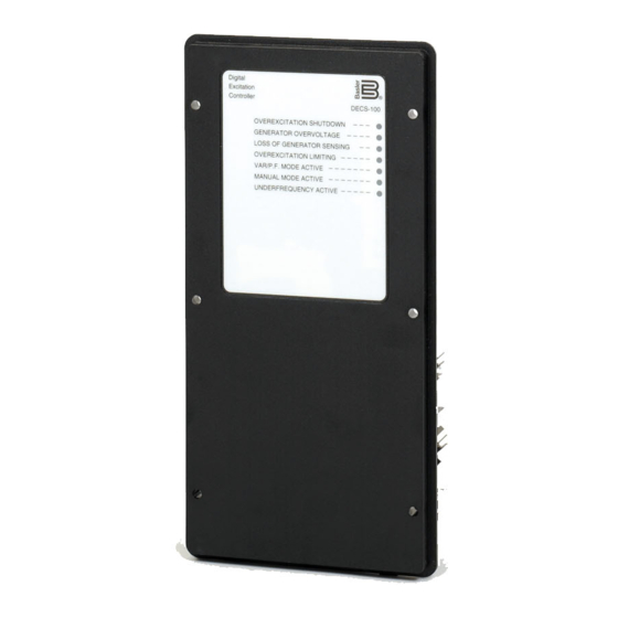
- Page 21 The DECS-100 human-machine interface (HMI) consists of front panel indicators and a rear-panel communication port. FRONT PANEL INDICATORS DECS-100 front panel indicators consist of eight red LEDs. The indicators are shown in Figure 2-1 and described in the following paragraphs. Figure 2-1. DECS-100 Front Panel Indicators...
- Page 22 DECS-100 is powered up following an underexcitation limiting shutdown. Var/P.F. Mode Active This LED lights to indicate that the DECS-100 is operating in the optional Var or Power Factor mode of control. Var/Power Factor control is enabled through BESTCOMS software and when the 52J/K contact input is open.
- Page 23 Field Overvoltage (Overexcitation Shutdown) ................3-5 Limiters ............................... 3-6 Overexcitation Limiting ........................3-6 Underexcitation Limiting ......................... 3-6 Soft Start ............................. 3-6 Voltage Matching (Optional) ....................... 3-6 Figures Figure 3-1. Simplified DECS-100 Block Diagram ..................3-1 9287500991 Rev K DECS-100 Functional Description...
- Page 24 This page intentionally left blank. DECS-100 Functional Description 9287500991 Rev K...
- Page 25 SECTION 3 • FUNCTIONAL DESCRIPTION INTRODUCTION This section describes how the DECS-100 functions and explains its operating features. To ease understanding, DECS-100 functions are illustrated in the block diagram of Figure 3-1. A detailed DECS-100 Function description of each function block is provided in the paragraphs under the heading of...
- Page 26 Closing a contact across terminals 52J and 52K disables var/power factor control. An open contact enables the DECS-100 to control the generator reactive power in either the var or the power factor mode. The contact has no effect when this function is not enabled in the software. For more information, see...
- Page 27 If the Voltage Matching option is enabled in the software, closing a contact across terminals VM and VMC causes the DECS-100 to operate in the voltage matching mode. An open contact disables voltage matching. Voltage matching is also disabled when either the 52J/K or 52L/M inputs are open.
- Page 28 Var Control Mode (Optional) In Var Control mode, the DECS-100 maintains generator vars (volt-amperes, reactive) at a set level when paralleling with an infinite bus. The DECS-100 calculates generator vars by using the sensed generator output voltage and current quantities.
- Page 29 If transfer to Manual is selected and a loss of sensing occurs, the relay output closes, and the DECS-100 transfers to the Manual mode of operation after the adjustable time delay expires. The DECS-100 will remain in this mode of operation until switched via BESTCOMS.
- Page 30 Its drawback is that it may not provide a smooth transition into and out of the limit. If hardware shutdown is enabled, the DECS-100 will be disabled when the time delay expires. When the DECS-100 is powered up following a shutdown triggered by overexcitation limiting, the Overexcitation Limiting indicator will light for five seconds.
- Page 31 DECS-100 voltage sensing inputs) are within the acceptable range, voltage matching can be achieved. The rate at which the DECS-100 matches the generator input level with the bus input level is controlled by a voltage matching speed setting. this setting is adjustable from 1 to 300 seconds in 0.01 second increments.
- Page 32 This page intentionally left blank. DECS-100 Functional Description 9287500991 Rev K...
- Page 33 Figure 4-10. Typical Connections for Station Power Application and Three-Phase Sensing ....4-12 Figure 4-11. Cross-Current (Reactive Differential) Connections ............. 4-13 Figure 4-12. Operating Power Connections for DECS-100 Programming (Input Voltage >120 Vac)..4-14 Tables Table 4-1. Bus Voltage Sensing Terminals ....................4-5 Table 4-2.
- Page 34 This page intentionally left blank. DECS-100 Installation 9287500991 Rev K...
-
Page 35: Section 4 • Installation
MOUNTING The DECS-100 is normally located in the generator conduit box. It is designed for behind the panel mounting and requires a cutout for front panel viewing. Supplied mounting hardware consists of six #12 thread-forming screws that pass through mounting holes in the conduit box and thread into the plastic shell of the DECS-100. - Page 36 Figure 4-1. DECS-100 Dimensions DECS-100 Installation 9287500991 Rev K...
- Page 37 Figure 4-2. Cutout and Drilling Dimensions 9287500991 Rev K DECS-100 Installation...
-
Page 38: Connections
IBM compatible PCs and hand-held computers. Figure 4-3 shows the terminal connections located on the rear panel of the DECS-100. Except as noted above, connections should be made with minimum wire size of 14 AWG. -
Page 39: Bus Voltage Sensing Inputs (Optional)
7. The other two terminals are connected to terminals 6U and 6D. This remote adjust switch may be mounted up to 150 feet away from the DECS-100 when using twisted, shielded cable. Only dry, ungrounded switching contacts should be applied to the Raise and Lower contact inputs. -
Page 40: Parallel Control And Var/Pf Control Inputs
Power input terminals are labeled 3, 4, and 5. Single-phase or three-phase power may be applied. Single- phase power may be applied to any two of the three terminals. The DECS-100 can be powered directly from a variety of sources as long as the DECS-100 input power specifications are followed (see Section 1, General Information, Specifications). -
Page 41: Communication Port
DECS-100 operating power is derived from a permanent magnet generator (PMG) and three-phase voltage sensing is applied to the DECS-100. Figure 4-7 shows another PMG application but with single-phase voltage sensing. Figure 4-8 shows an application where DECS-100 operating power is derived from the generator output (shunt application) and three-phase voltage sensing is applied to the DECS-100. - Page 42 Figure 4-6. Typical Connections for PMG Application with ABC Rotation and Three-Phase Sensing DECS-100 Installation 9287500991 Rev K...
- Page 43 Figure 4-7. Typical Connections for PMG Application with ABC Rotation and Single-Phase Sensing 9287500991 Rev K DECS-100 Installation...
- Page 44 Figure 4-8. Typical Connections for Shunt Application with ABC Rotation and Three-Phase Sensing 4-10 DECS-100 Installation 9287500991 Rev K...
- Page 45 Figure 4-9. Typical Connections for Shunt Application with ABC Rotation and Single-Phase Sensing 9287500991 Rev K DECS-100 Installation 4-11...
- Page 46 Figure 4-10. Typical Connections for Station Power Application and Three-Phase Sensing 4-12 DECS-100 Installation 9287500991 Rev K...
-
Page 47: Installation For Ce Compliance
Lethal voltage is present at the rear panel when the unit is energized. Rear panel connections should be made only when the unit is de-energized. 1. Tag and disconnect all wiring to the DECS-100. Be sure to insulate the wire terminals to prevent a short circuit. -
Page 48: Operating Power Considerations During Decs-100 Programming
7. Connect the rest of the DECS-100 leads using the tagged identification. 8. Start the prime mover/generator and perform the final adjustments at rated speed and load. 9. After the initial startup, the DECS-100 should not require any further adjustments unless there is a change in the system. - Page 49 SECTION 5 • BESTCOMS SOFTWARE ....................5-1 INTRODUCTION............................ 5-1 INSTALLATION............................5-1 Installing BESTCOMS ........................5-1 Connecting the DECS-100 and PC ....................5-1 STARTING BESTCOMS ........................5-1 Establishing Communication ......................5-2 CHANGING SETTINGS ......................... 5-2 SENDING AND RECEIVING SETTINGS ....................5-3 Sending Settings ..........................
- Page 50 Figure 5-20. Password Dialog Box ......................5-21 Figure 5-21. Software Uploading Advisory Dialog Box ................5-22 Figure 5-22. DECS-100 Embedded Program Loader ................5-22 Figure 5-23. Retrieved DECS-100 Information ..................5-22 Figure 5-24. Settings File Reminder Dialog Box ..................5-23 Figure 5-25.
-
Page 51: Section 5 • Bestcoms Software
BESTCOMS. Software within BESTCOMS enables the user to establish proper PID (proportional + integral + derivative) parameters based on a specified generator and/or exciter time constants. Within BESTCOMS, DECS-100 settings can be saved in a computer file and used later to configure other units with the same settings. -
Page 52: Establishing Communication
Once all desired setting changes have been made on a setting group screen, the settings must be sent to the DECS-100 before viewing other screens. Otherwise, the settings changes will be lost. Settings changes can be sent to the DECS-100 by clicking the SendToDECS button. -
Page 53: Sending And Receiving Settings
Settings are saved in nonvolatile memory (EEPROM). In the event of a power loss, these are the settings that are active at power up. If settings are changed and sent to the DECS-100, but not sent to EEPROM, the changed settings are lost if DECS-100 operating power is lost. When exiting BESTCOMS or closing communication, you are asked if you want to save the settings to EEPROM. -
Page 54: Setting Adjustments
This setting field reads and displays the nominal output of the current transformer (CT) that supplies the DECS-100 with B-phase generator line current. This value (1 or 5) must be manually entered for units with a firmware version lower than 1.12.01. -
Page 55: Startup Tab
Voltage Matching - Speed (sec). This setting determines how quickly the generator voltage is adjusted by the DECS-100 to match the bus voltage. The Speed setting is adjustable from 1 to 300 seconds in 0.01 increments. Voltage Matching – Disable by Contact. -
Page 56: Control Gain
The voltage matching mode can be Maintain or Revert. When Maintain is selected, the DECS-100 setpoint is maintained at the bus voltage level even after the generator or utility breaker opens. When Revert is selected, the DECS-100 setpoint reverts to its original level when the generator or utility breaker opens. - Page 57 Figure 5-9. Control Gain Screen Table 5-1. DECS-100 Stability Range Settings Time Constants Generator Stability Size Generator (T’do) Exciter (Texc) Range SMALL 0.17 0.25 0.33 0.42 0.50 0.58 0.67 0.75 0.83 0.92 1.00 1.08 1.17 1.25 1.33 1.42 1.50 1.58 10.0...
-
Page 58: Analysis
VAR/PF - PF Integral Gain KI. This setting adjusts the integral gain and determines the characteristic of the DECS-100 dynamic response to a changed PF setting. PF KI values of 0 to 1,000 may be entered in increments of 0.01. -
Page 59: Fcr Tab
Figure 5-11 illustrates the settings, sensing values, and alarm signal indicators of the FCR tab. The settings of the FCR tab make it possible to increment and decrement the FCR setpoint of the DECS-100. The sensing values and alarm signal indicators of the FCR tab are also displayed by the other tabs of the Analysis screen. -
Page 60: Pf Tab
FCR Setpoint field is selected by clicking the adjacent pushbutton. Clicking this button sends the FCR Setpoint value to the DECS-100 and changes the color of the pushbutton from gray to red. Field Current Step Response - Increment of FCR Setpoint (A). -
Page 61: Var Tab
FCR Setpoint field is selected by clicking the adjacent pushbutton. Clicking this button sends the PF setpoint value to the DECS-100 and changes the color of the pushbutton from gray to red. Power Factor Step Response - Increment of PF Setpoint. -
Page 62: Protection Settings
Meter Value field or selected by dragging the dial pointer to the desired value. The new value is sent to the DECS-100 by clicking the Send button. -
Page 63: Protection Tab
The value in this field is adjustable from 0 to 250 Vdc and determines the field voltage level that will cause the DECS-100 to issue an overexcitation limit alarm. When the field voltage increases above the value of this field for 10 seconds, the Overexcitation Shutdown LED on the front panel lights. -
Page 64: Limiter Tab
The value of current in this field determines the excitation level that will cause the DECS-100 to issue an overexcitation limit alarm. A current level of 0 to 15 A may be entered in 0.01 increments. When the level of field current increases above the value of this field, the Overexcitation Shutdown LED on the front panel lights and the OEL time delay starts timing down. -
Page 65: Operation Tab
PT ratio. All metering values are updated once each second. When single-phase sensing is used (System Configuration screen, Sensing Voltage) and the DECS-100 sensing voltage terminals (E1, E2, and E3) are connected as shown in Figures 4-7 or 4-9, all of the generator voltage metering values will be identical. - Page 66 Power Factor Control (PF) - PF Setpoint. Power Factor setpoint values are adjustable from -0.6 to -1 (1) or 0.6 to +1 in 0.001 increments. The background color of this field is green when the DECS-100 is operating in AVR mode and is regulating the power factor setpoint.
-
Page 67: Alarm/Status Tab
External Adjust terminals (6D and 7 to decrease, 6U and 7 to increase) of the DECS-100. For AVR mode, each click of the Raise button increases the voltage setpoint 0.01 volts; each click of the Lower button decreases the voltage setpoint 0.01 volts. -
Page 68: Pid Data
PID stands for Proportional, Integral, Derivative. The word proportional means that the response of the DECS-100 output is proportional or relative to the amount of change that is observed. Integral means that the DECS-100 output is proportional to the amount of time that a change is observed. Integral action eliminates offset. -
Page 69: Adding To The Pid List
BESTCOMS software enables you to print a list of DECS-100 settings, save DECS-100 settings to a file, and open a settings file and upload those settings to a DECS-100. A settings file may also be opened and edited within any text editing software. -
Page 70: Saving Settings Files
A DECS-100 settings file downloaded from a DECS-100 or created within BESTCOMS can be uploaded to multiple DECS-100 units. Only a DECS-100 settings file with a .de1 extension can be uploaded to a DECS-100 unit. Before uploading a file, communication must be initiated with the DECS-100 that is to Starting BESTCOMS, Establishing Communication receive the settings. -
Page 71: Terminating Communication
Close Comm Port. You are asked if you want to save the settings to EEPROM. This question is asked even if no changes were made to the DECS-100 settings. When you execute the Close command (with a Yes or No to save settings to EEPROM), communication with the DECS-100 is terminated. If you choose to exit BESTCOMS (by clicking File on the menu bar and then Exit) without first closing communication, you are still given the opportunity to save the settings to EEPROM. - Page 72 5. Click the Start Transfer Data button to proceed with software uploading. The dialog box of Figure 5- 24 appears and recommends that your DECS-100 settings be saved in a file that can be uploaded to the DECS-100 after the embedded firmware is updated.
- Page 73 Figure 5-24. Settings File Reminder Dialog Box Clicking No allows you to exit the upload process so that a DECS-100 settings file can be created. Refer to the Settings Files subsection for information about creating a settings file. Clicking Yes continues with the upload process and displays the Open dialog box of Figure 5-25. The Open dialog box is used to locate and select the appropriate file for uploading to the DECS-100.
- Page 74 Figure 5-27. DECS-100 Information After Upload 7. Close the DECS-100 Embedded Program Loader. BESTCOMS loads the default settings, loads the saved settings, and checks the settings. 5-24 DECS-100 BESTCOMS Software 9287500991 Rev K...
- Page 75 Loss of Generator Sensing Indicator is Annunciating ................ 6-5 Overexcitation Limiting Indicator is Annunciating ................6-5 Underexcitation Limiting Indicator is Annunciating ................6-5 Underfrequency Active Indicator is Annunciating ................6-6 No Droop ............................6-6 No Voltage Matching .......................... 6-7 9287500991 Rev K DECS-100 Maintenance and Troubleshooting...
- Page 76 This page intentionally left blank. DECS-100 Maintenance and Troubleshooting 9287500991 Rev K...
-
Page 77: Section 6 • Maintenance And Troubleshooting
TROUBLESHOOTING If you do not get the results that you expect from the DECS-100, first check the programmable settings for the appropriate function. Use the following troubleshooting procedures when difficulties are encountered in the operation of your excitation system. -
Page 78: Low Generator Output Voltage
Step 7. Verify that the DECS-100 soft start settings are correct. Too long of a soft start setting may give the appearance of no buildup. If the soft start settings are incorrect, adjust the settings. If the soft start settings have no effect, proceed to Step 8. - Page 79 If the voltage adjustment is too high, adjust it to the correct setpoint. If the voltage adjustment is correct, proceed to Step 2. 9287500991 Rev K DECS-100 Maintenance and Troubleshooting...
-
Page 80: Poor Voltage Regulation
Step 1. Verify that the case of the DECS-100 is properly grounded. If the DECS-100 is not properly grounded, connect a dedicated ground wire to the quarter-inch fast-on connector labeled GND on the rear of the DECS-100 case. If the DECS-100 is properly grounded, proceed to Step 2. -
Page 81: Overexcitation Shutdown Indicator Is Annunciating
Verify that the generator exciter field voltage requirements are compatible with the DECS-100. If the exciter field voltage requirements are not compatible with the DECS-100, contact Basler Electric Customer Service for recommendations. If the exciter field voltage requirements are compatible with the DECS-100, proceed to Step 3. Step 3. Replace the DECS-100. -
Page 82: Underfrequency Active Indicator Is Annunciating
If the 52L/M contact input is open, proceed to Step 2. Step 2. Verify that the DECS-100 52J/K contact input (if present) is closed or the Var/PF function is disabled via BESTCOMS. Var/PF operation must be disabled for droop operation. If var/PF operation is disabled, proceed to Step 3. -
Page 83: No Voltage Matching
If the interconnection is incorrect, reconnect according to the appropriate interconnect diagram. If the interconnection is correct, check for open system fuses. Verify that the potential sensing transformer, if used, is connected to DECS-100 terminals B1 and B3. If potential sensing transformer connections are correct, proceed to Step 5.
Need help?
Do you have a question about the DECS-100 and is the answer not in the manual?
Questions and answers