Sign In
Upload
Manuals
Brands
Bartec Manuals
Control Unit
APEX px
Bartec APEX px Manuals
Manuals and User Guides for Bartec APEX px. We have
1
Bartec APEX px manual available for free PDF download: Operating Instructions Manual
Bartec APEX px Operating Instructions Manual (98 pages)
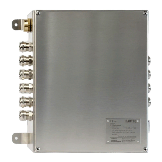
Manual Ex p Control Unit
Brand:
Bartec
| Category:
Control Unit
| Size: 6.33 MB
Table of Contents
Table of Contents
4
1 About These Operating Instructions
8
Highlighting in the Document
9
Warnings
9
Symbols and Icons
10
Technical Changes
10
Languages
10
2 Safety
11
Intended Use
11
Exclusive Purpose
11
Improper Use
11
Qualification of Staff
11
Warranty
12
Safety Instructions
13
General
13
Safety Instructions for Operation
13
Avoidance of Damage to Property
14
Short Circuit Due to Improper Connection
14
Triggering the Safety Function
14
EMC-Compliant Connection
14
Storage at an Excessively High Temperature
14
Aggressive Cleaning Agents
15
Danger to Health Due to Improper Disposal
15
Obligations of the Owner
15
Instructions for Use
15
Marking and Test Certificate
16
Ex P Control Unit APEX, Type 07-37A2-2**1/*520
16
Standards Complied with
16
Ex P Control Unit APEX, Type 07-37A2-2211/*520
16
SIL Qualification / Safety According to IEC 61508
17
SIL Qualification
17
Safety Function
18
Safety Parameters
18
Reaction Time
19
Residual Risk
19
3 Product Description
20
General Information
20
Ex P Control Units APEX
20
APEX Design, Type 07-37A2-2211/*520
21
Accessories
22
Valve Fuse
22
Pressure Monitor
22
Purge Gas Valve
22
P-Operator Panel
22
Programming Switch
23
Programming Cable
23
4 Transport and Storage
24
Scope of Delivery
24
Packaging
24
Transport
24
Storage
25
Disposal
25
5 Installation
26
Installation Ex P Control Unit, Type 07-37A2-2211/*520
26
Installation of the Pressure Monitor
26
Assembly "Internal Mounting Kit, Type 05-0091-0275
27
Assembly "External Mounting Kit, Type 05-0091-0280
28
Installation Purging Gas Supply
29
Version G1/4
30
Version G1/2
31
Version G1/4" (Dust Application)
32
Pneumatic Connections
33
Pneumatic Connections APEX, Type 07-37A2-2211/*520
33
Pneumatic Connections Pressure Outlet Module, Type 17-51P3-1*03
33
Typical Installations
33
Typical Arrangement - Outside Installation / Gas Application
34
Typical Arrangement - Inside Installation / Gas Application
35
Typical Arrangement - Outside Installation / Dust Application
36
Typical Arrangement - Inside Installation / Dust Application
37
6 Electrical Connections
38
General
39
Connection Notes
39
EMC-Compliant Connection
40
Pre-Fuse
41
Inductive Loads
42
Electrical Wiring APEX
43
Ex E" Connection Terminals
44
Connection Terminals "Ex I
48
7 Operation
54
WEB Interface
54
Adjusting the LAN Connection
54
Operation of the WEB Interface
56
Logging Onto the WEB Interface
56
Navigation in the WEB Interface
56
Input of Parameters
57
LED Indicators
57
Menu Structure WEB-Interface
58
WEB-Interface Operating Menu
59
Purge Parameter
59
Start Page
62
Status
63
Messages
63
Parameter
63
Error Log
64
Temperature Sensors
64
Extended
66
Menu „Network
70
Menu „Language
70
System Status
71
Reading Container Data
72
8 Commissioning
73
General
73
Sequence for the Settings
73
Parameterization of Purge Gas Valve
73
Setting for "Leakage Air Compensation" Digital Valves
74
Configuration for Gas Applications
74
Ex P Settings - Manual Purge
74
Ex P Settings - Automatic Purge
78
Configuration for Dust Applications
81
Ex P Settings
81
9 Functional Test and Procedure
83
Safety During Operation
83
Functional Flow Diagram for the Ex P Control Station
83
Ex P Control Flow Chart
83
Functional Flow Diagram - Dust
84
10 Maintenance and Care
85
Types of Purging Gas
85
Maintenance Work
85
Maintenance Intervals
85
Visual Inspection
86
Cleaning
86
Regular Maintenance
86
Repairs
86
Faults and Troubleshooting
86
Faults
87
Error Messages
89
11 Technical Data
91
12 Order Numbers
92
Ex P Control Unit APEX, Standard
92
Pressure Monitor Module
92
Valve Fuse
92
Purge Gas Valve
92
Operator Panel
92
Installation Accessories
92
Protective Circuits
92
13 Annex
93
Purge Diagram
93
Purge Diagram, Single Outlet Device
93
Purge Diagram, Double Outlet Device
93
Sequence Diagram
94
Dimensions
95
Ex P Control Unit APEX Px , 07-37A2-2211/*520
95
Pressure Outlet, 17-51P3-1*03
95
Software Packages Used
96
14 Declaration of Conformity
97
Ex P Control Unit APEX, Type 07-37A2-*2*1
97
Advertisement
Advertisement
Related Products
Bartec APEXmpc
Bartec A7-37S2-2111/M5
Bartec APEX (APC) 07-3704 Series
Bartec Agile X IS
Bartec Agile
Bartec Agile S Series
Bartec SILAS A7-3741-1110/1000
Bartec SILAS A7-3741-1110/4000
Bartec SILAS A7-3741-1110/2000
Bartec SILAS A7-3741-1110 Series
Bartec Categories
Measuring Instruments
Control Unit
Handhelds
Enclosure
Tablet
More Bartec Manuals
Login
Sign In
OR
Sign in with Facebook
Sign in with Google
Upload manual
Upload from disk
Upload from URL