Banner SC22-3 Safety Controller Manuals
Manuals and User Guides for Banner SC22-3 Safety Controller. We have 4 Banner SC22-3 Safety Controller manuals available for free PDF download: Instruction Manual, Quick Start Manual
Banner SC22-3 Instruction Manual (122 pages)
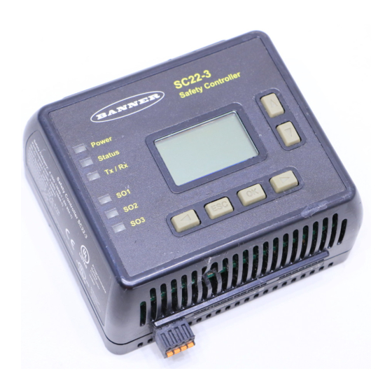
Safety Controller
Brand: Banner
|
Category: Controller
|
Size: 6 MB
Table of Contents
Advertisement
Banner SC22-3 Instruction Manual (122 pages)
Brand: Banner
|
Category: Controller
|
Size: 3 MB
Table of Contents

Banner SC22-3 Instruction Manual (128 pages)
Safety Controller
Brand: Banner
|
Category: Controller
|
Size: 11 MB
Table of Contents
Advertisement

Banner SC22-3 Quick Start Manual (16 pages)
Safety Controller
Brand: Banner
|
Category: Controller
|
Size: 2 MB