Sign In
Upload
Manuals
Brands
Bacharach Manuals
Security Sensors
H25-IR PRO
Bacharach H25-IR PRO Manuals
Manuals and User Guides for Bacharach H25-IR PRO. We have
2
Bacharach H25-IR PRO manuals available for free PDF download: User Manual, Manual
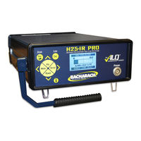
Bacharach H25-IR PRO User Manual (128 pages)
Infrared Refrigerant Gas Leak Detector
Brand:
Bacharach
| Category:
Security Sensors
| Size: 6 MB
Table of Contents
Table of Contents
3
Chapter 1: Introduction
11
Product Overview
11
Conventions Used in this Manual
11
Safety Precautions
12
Features and Capabilities
13
Functional Overview
13
Key System Components
13
Operation Modes: Search Vs. Measure
14
Figure 1-1. Toggling between Search and Measure Modes
14
Operational Functions/Features
15
Table 1-1. H25-IR PRO Functions and Features
15
Advanced Leak Quantification (Alqä) Technology
16
Using a Reference Leak Source
16
Figure 1-2. H25-IR Pro's Alqä Technology
17
Figure 1-3. Adjusting the H25-IR Pro to a Recognized Leak Standard
18
Specifications
19
Table 1-2. Specifications
19
Chapter 2: Hardware Overview
21
Unpacking
21
External Components
21
Front Panel
21
Figure 2-1. Front Panel Components of the H25-IR PRO
21
Back Panel
22
Probes and Hoses
22
Standard Probe with Flexible Tubing
22
Figure 2-2. Back Panel Components of the H25-IR PRO
22
Figure 2-3. Components of the Standard Probe with Flexible Tubing
22
Standard Probe with LED and Push Button
23
Figure 2-4. Components of the Standard Probe with LED and Push Button
23
Table 2-1. H25-IR PRO Standard Probe Components
23
Table 2-2. H25-IR PRO Standard Probe Components
23
Smart Probe
24
Figure 2-5. Components of the Smart Probe
24
Connecting the Flexible Probe Tube
25
Figure 2-6. H25-IR PRO Smart Probe Key Lock Feature
25
Table 2-3. H25-IR PRO Smart Probe Components
25
Table 2-4. Connecting the Flexible Probe Tube
25
Power Cord
26
Figure 2-7. Connecting the Probe to the H25-IR PRO
26
Figure 2-8. Connecting the Power Cord to the H25-IR PRO
26
Internal Components
27
NDIR Sensor
27
Figure 2-9. NDIR Optical Sensor
27
Chapter 3: Menu System Overview
28
Menu Architecture
28
Figure 3-1. the Menu Interface (Display and Buttons): a Key User Interface with a Menu-Driven Architecture
28
Table 3-1. Key Components of the Menu Structure
29
Menu Navigation
30
Overview
30
Figure 3-2. Arrows Indicating Additional Menus, Menu Items, and Parameter Editing Options
30
Figure 3-3. Menu Architecture Summary
31
Figure 3-4. Front Panel Components with Sample Display
31
Front Panel Buttons
32
Changing Values of Menu Items
32
Table 3-1. Front Panel Buttons
32
Configuration-Dependent Menu Items
33
Figure 3-5. Examples of Value Types
33
Figure 3-6. PROBE BUTTON Menu Item Based on Probe Style Ordered
33
Special Key Combinations
34
Version Screen (at Power Up)
34
Figure 3-7. Version Screen at Power up
34
Table 3-2. Common Key Combinations
34
Setup Summary Screen (Warm-Up)
35
Search Mode Screen
35
Figure 3-8. Setup Summary Screen Showing 60-Second Initialization Countdown
35
Figure 3-9. Sample Search Mode Screens (Showing Graphic and Numeric Display Styles)
35
Measure Mode Screen
36
Basic Setup Screen
36
Figure 3-10. Sample Measure Mode Screen
36
Figure 3-11. Basic Setup Screen
36
Advanced Setup Screen
37
Figure 3-12. Advanced Setup Screen
37
Diagnostics Screen
38
Figure 3-13. Diagnostics Screen
38
Chapter 4: Wiring
40
Introduction
40
Relay Connections
40
Figure 4-1. Sample Relay Wiring
40
4-20Ma Current Loop Connection
41
Figure 4-2. 4-20Ma Loop Connector Used
41
Communications Connection
42
Standard Versus Smart Probe Wiring
42
Table 4-1. RS-232 Communications Settings
42
Figure 4-3. Front Panel Printed Circuit Board Containing Probe Connectors J2 and J7
43
Table 4-2. Procedure to Change Factory-Set Probe Configuration
43
Chapter 5: Operation
44
Introduction
44
Table 5-1. Function Reference
45
Turning on the H25-IR PRO
46
Search Mode Screen
46
Overview
46
Display Styles (Graphic Vs. Numeric)
46
Figure 5-1. Sample Search Mode Screens (Showing Graphic and Numeric Display Styles)
46
Table 5-2. Turning on the H25-IR PRO
46
Mode Button
47
Figure 5-2. Toggling between Search Mode and Measure Mode (Example 1)
47
Figure 5-3. Toggling between Search Mode and Measure Mode (Example 2)
47
Volume Button
48
Range Button
48
Table 5-3. Changing the Volume Setting
48
Setup (and Right Arrow) Button
49
Figure 5-4. Sample 2X, 3X, and 4X Range Displays in the Graphic SEARCH MODE Screen
49
Table 5-4. Accessing the Main Menu Screens Using the Setup Button
50
Zero (ENT) Button
51
Information (I) Button
51
Figure 5-5. Sample Search and Measure Screens before Zeroing
51
Figure 5-6. Sample Search and Measure Screens Shortly after Zeroing
51
Measure Mode Screen
52
Overview
52
Figure 5-7. Sample Measure Mode Screen
52
Log (Esc) Button
53
Figure 5-8. Graphical Representation of the Measurement Log
53
Table 5-5. Logging Data
54
Basic Setup Screen
55
Table 5-6. Accessing the BASIC SETUP Screen
55
Gas Type
56
Table 5-7. Setting the Gas Type from the List of Standard Gases
56
Table 5-8. Gas Type Menus and Selection
57
Table 5-10. Leak Rate Conversion Chart
58
Table 5-9. Display Units Available in the H25-IR PRO
58
Unit Display
58
Alarm Setpoint
59
Table 5-11. Changing the Unit Display Setting
59
Table 5-12. Changing the Alarm Setpoint
60
Display Style
61
Figure 5-9. Samples of Graphic and Numeric Display Styles
61
Table 5-13. Changing the Display Style
62
Advanced Setup Screen
63
Table 5-14. Accessing the ADVANCED SETUP Screen
63
Figure 5-10. Options of the Advanced Setup Screen
64
User Setups 1-4
64
Figure 5-11. Weighing Your Application Needs: When to Use User Setup 0 (Default) Vs. User Setups 1-4
65
Table 5-15. Accessing the USER SETUP Screens 1-4
65
Table 5-16. Changing a User Setup Name
66
Figure 5-12. Sample Search Screen (with User Setup Active) Showing User Name "FREEZER 1
67
Table 5-17. Changing a User Setup Gas Type
67
Table 5-18. Changing a User Setup Alarm Setpoint
68
Table 5-19. Changing a User Setup Feedback Mode
70
Relay Settings Screen
71
Table 5-20. Accessing the RELAY SETTING Screen
71
Measurement Log
73
Table 5-21. Relay Setting Options
73
Table 5-22. Accessing the Measurement Log
74
Date/Time Set
75
Table 5-23. Setting the Date and Time
75
Log Limit
76
Table 5-24. Setting the Log Limit
76
Loop Factor
78
Table 5-25. Default Loop Factor Mapping Example (0.016 Ma = 1 PPM)
78
Table 5-26. Changing the Loop Factor
78
Serial Data
80
Table 5-27. Serial Data Options
80
Table 5-28. Changing the Serial Data Setting
80
Probe Button (Optional)
81
Table 5-29. Assign Probe Button Options
81
Figure 5-13. Advanced Setup Screen Without (Left) and with (Right) a Detected Smart Probe
82
Table 5-30. Changing the Probe Button Setting
83
Diagnostics Screen
84
Table 5-31. Accessing the Diagnostics Screen (Method #1)
84
Table 5-32. Accessing the DIAGNOSTICS Screen (Method #2)
85
Current Faults Screen
87
Table 5-33. Accessing the Current Faults Screen
87
Table 5-34. Fault Codes
88
Sensor Data Screen
89
Table 5-35. Accessing the Sensor Data Screen
89
Table 5-36. Sensor Data Parameters and Sample Values
90
Adjustment to a Known External Leak Source
91
Table 5-37. Adjusting the H25-IR PRO to a Known External Leak Source
91
Custom Gas Type Configuration
93
Figure 5-14. Locked Message for Subsequent Attempts at External Adjustment
93
Factory Gas Type Configuration
94
Table 5-38. Configuring the H25-IR PRO to Use a Factory Gas Type
94
Chapter 6: Maintenance
98
Fuse Replacement
98
Table 6-1. Items Required for Fuse Replacement
98
Table 6-2. Fuse Replacement Procedure
98
Probe Tip Filter Replacement
99
Figure 6-1. Location of Fuse Holder
99
Table 6-3. Items Required for Probe Tip Filter Replacement
99
Table 6-4. Probe Tip Filter Replacement Procedure
99
Probe "O" Ring Replacement
100
External Filter Replacement
100
Figure 6-2. Probe Filter and "O" Ring Locations
100
Table 6-5. Items Required for "O" Ring Replacement
100
Table 6-6. Probe "O" Ring Replacement Procedure
100
Table 6-7. Items Required for External Filter Replacement
100
Table 6-8. External Filter Replacement Procedure
100
Figure 6-3. Back Panel of the H25-IR Pro Showing Proper Orientation of the External Filter
101
NDIR Sensor Replacement
102
Figure 6-4. Removing the Top Cover
102
Table 6-9. Items Required for NDIR Sensor Replacement
102
Table 6-10. Replacement NDIR Sensor Kit
102
Table 6-11. NDIR Sensor Replacement Procedure
102
Figure 6-5. NDIR Sensor Showing Three Cable Ties Removed
103
NDIR Sensor Adjustment
105
Spare Parts and Accessories
105
Table 6-12. Spare Parts and Accessories
105
Firmware Upgrade Procedure
106
Table 6-13. Items Required for Upgrading Firmware
106
Table 6-14. Firmware Upgrade Procedure
106
Chapter 7: Troubleshooting
110
Diagnostics
110
Service Centers
110
Table 7-1. Common Concerns
110
System Faults
111
Table 7-2. Fault Codes
111
Appendix A: Glossary of Terms
112
Table A-1. Glossary of Terms
112
Appendix B: Acronyms and Abbreviations
114
Table B-1. Acronyms and Abbreviations
114
Appendix C: Supported Gas Types
116
Basic Gas Types
116
Table C-1. Basic (Primary) Gas Types
116
Factory Gas Types
118
Table C-2. Factory (Secondary) Gas Types
119
Appendix D: Declaration of Conformity
121
Index
121
Advertisement
Bacharach H25-IR PRO Manual (10 pages)
Brand:
Bacharach
| Category:
Gas Detectors
| Size: 1 MB
Table of Contents
Section 1: Introduction
2
Required Tools
2
Section 2: Replacement Process
4
Rear Plate Removal
4
Section 3: Maintenance
8
Service Centers
9
Advertisement
Related Products
Bacharach H-25C
Bacharach H-10 PRO
Bacharach H25-IR
Bacharach H-10G
Bacharach H-10PA
Bacharach H-SEM
Bacharach Halogen Monitor
Bacharach HGM-MZ
Bacharach HFO1233ZD
Bacharach HFO1234YF
Bacharach Categories
Measuring Instruments
Test Equipment
Gas Detectors
Security Sensors
Controller
More Bacharach Manuals
Login
Sign In
OR
Sign in with Facebook
Sign in with Google
Upload manual
Upload from disk
Upload from URL