Sign In
Upload
Manuals
Brands
AXIOMATIC Manuals
Controller
AX030210
AXIOMATIC AX030210 Manuals
Manuals and User Guides for AXIOMATIC AX030210. We have
1
AXIOMATIC AX030210 manual available for free PDF download: User Manual
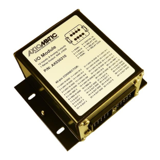
AXIOMATIC AX030210 User Manual (86 pages)
12 Input, 8 Signal Output & 1 Relay Output Controller with CANopen
Brand:
AXIOMATIC
| Category:
Controller
| Size: 3 MB
Table of Contents
Table of Contents
5
Overview of the Controller
13
Figure 1 - AX030210 Block Diagram
13
Controller Function Blocks
15
Input Function Blocks
15
Table 1 - Object 6112H - AI Operating Mode Options
15
Table 2 - Object 6110H - AI Sensor Type Options
15
Figure 2 - Analog Input Objects
15
Table 3 - AI Input Range Options Depending on Sensor Type
16
Table 4 - DI Debounce Filter Options
16
Table 5 - Object 61A0H - AI Filter Type Options
17
Figure 3 - Digital Input Debouncing
17
Table 6 - Object 2102H AI Decimal Digits FV Depending on Sensor Type
18
Figure 4 - Analog Input Linear Scaling FV to PV
18
Table 7 - AI Object Defaults Based on Sensor Type and Input Range
19
Table 8 - AI Object Ranges Based on Sensor Type and Input Range
20
Resistive Input
21
Digital Input
21
Table 9 - DI Pullup/Down Options
21
Figure 5 - Digital Input Objects
21
Table 10 - Object 6002H DI Polarity 8 Input Lines Options
22
Figure 6 - Discrete Input Hysteresis
22
Output Function Blocks
23
Figure 7 - Analog Input Reads as Digital
23
Figure 8 - Analog Output Objects
23
Table 11 - Object 6310H AO Output Type Options
24
Table 12 - AO Output Range Options Depending on Output Type
24
Table 13 - AO Object Defaults Based on Output Type and Input Range
24
Relay Output
25
Figure 9 - Analog Output Linear Scaling PV to FV
25
Reference Voltages
26
PID Function Block
26
Figure 10 - PID Control Objects
26
Table 14 - PID Control Response Options
27
Figure 11 - PID Control Algorithm
27
Lookup Table Function Block
28
Figure 12 - Lookup Table Objects
28
X-Axis, Input Data Response
29
Y-Axis, Lookup Table Output
29
Point to Point Response
29
Figure 13 - Lookup Table Defaults with Ramp and Step Responses
30
Figure 14 - Lookup Table Examples to Setup for Dual-Slope Joystick Deadband Response
30
X-Axis, Time Response
31
Table 15 - Ltyz Point Response Options
31
Programmable Logic Function Block
32
Figure 15 - Logic Block Objects
32
Figure 16 - Logic Block Flowchart
34
Conditions Evaluation
35
Table 16 - LB(X-3) Condition Structure Definition
35
Table 17 - LB(X-3) Condition Operator Options
35
Table 18 - LB(X-3) Condition Evaluation Results
36
Table 19 - LB(X-3) Function Logical Operator Options
36
Table 20 - LB(X-3) Conditions Evaluation Based on Selected Logical Operator
37
Logic Block Output
38
Table 21 - LB(X-3) Default Lookup Tables
38
Math Function Block
39
Figure 17 - Math Function Block Objects
39
Table 22 - Object 4Y50H Math Function Operators
40
Miscellaneous Function Block
41
Figure 18 - Miscellaneous Objects
41
Available Control Sources
43
Table 23 - Available Control Sources and Numbers
43
Diagnostics
44
Table 24 - Scaling Limits Per Control Source
44
Table 25 - EMCY Codes
44
Installation Instructions
45
Dimensions and Pinout
45
Table 26 - AX030211 Connector Pinouts
45
Figure 19 - AX030211 Dimensional Drawing
45
Canopen Interface and Object Dictionary
46
Node ID and Baud Rate
46
LSS Protocol to Update
46
Setting Node-ID
46
Setting Baud Rate
47
Table 27 - LSS Baud Rate Indices
48
Communication Objects (DS-301)
50
1000H Device Type
51
1001H Error Register
51
1002H Manufacturer Status Object
51
1003H Pre-Defined Error Field
51
1010H Store Parameters
51
1011H Restore Parameters
52
1016H Consumer Heartbeat Time
52
1017H Producer Heartbeat Time
52
1018H Identity Object
52
1020H Verify Configuration
52
1029H Error Behavior
53
1400H RPDO 1 Communication Parameters
53
1401H RPDO 2 Communication Parameters
53
1402H RPDO 3 Communication Parameters
53
1403H RPDO 4 Communication Parameters
53
1600H RPDO 1 Mapping Parameters
54
1601H RPDO 2 Mapping Parameters
54
1602H RPDO 3 Mapping Parameters
54
1603H RPDO 4 Mapping Parameters
54
1800H TPDO 1 Communication Parameters
54
1801H TPDO 2 Communication Parameters
55
1802H TPDO 3 Communication Parameters
55
1803H TPDO 4 Communication Parameters
55
1A00H TPDO 1 Mapping Parameters
55
1A01H TPDO 2 Mapping Parameters
55
1A02H TPDO 3 Mapping Parameters
56
1A03H TPDO 4 Mapping Parameters
56
Application Objects
57
6000H DI Read State 8 Input Lines
58
6002H DI Polarity 8 Input Lines
58
6110H AI Sensor Type
58
6112H AI Operating Mode
58
6132H AI Decimal Digits PV
58
61A0H AI Filter Type
59
61A1H AI Filter Constant
59
6302H AO Decimal Digits PV
59
6310H AO Output Type
59
6332H AO Decimal Digits FV
59
6340H AO Fault Mode
59
6458H PID Physical Unit Timing
59
6459H PID Decimal Digits Timing
60
7100H AI Input Field Value
60
7120H AI Input Scaling 1 FV
60
7121H AI Input Scaling 1 PV
60
7122H AI Input Scaling 2 FV
60
7123H AI Input Scaling 2 PV
60
7130H AI Input Process Value
60
7148H AI Input Span Start
61
7149H AI Input Span End
61
7300H AO Output Process Value
61
7320H AO Output Scaling 1 PV
61
7321H AO Output Scaling 2 FV
61
7323H AO Output Scaling 2 FV
62
7330H AO Output Field Value
62
7341H AO Output Fault FV
62
7450H PID Proportional Band
62
7452H PID Integral Action Time
62
7454H PID Derivative Action Time
62
7456H PID Cycle Time
62
Manufacturer Objects
63
2020H DI Pull up down Mode 1 Input Line
65
2100H AI Input Range
65
2101H AI Number of Pulses Per Revolution
65
2102H AI Decimal Digits FV
65
2103H AI Debounce Filter
65
2110H AI Error Detect Enable
65
2111H AI Error Clear Hysteresis
66
2112H AI Error Reaction Delay
66
2302H AO Output Range
66
2330H AO Ramp up
66
2331H AO Ramp down
66
2340H AO Control Input Source
66
2341H AO Control Input Number
67
2350H AO Enable Input Source
67
2351H AO Enable Input Number
67
2352H AO Enable Response
67
2353H AO Disable Drive FV
67
2360H AO Override Input Source
68
2361H AO Override Input Number
68
2362H AO Override Response
68
2450H PID Tolerance
68
2451H PID Integral Gain
68
2452H PID Derivative Gain
68
2453H PID Target Source
69
2454H PID Target Number
69
2455H PID Feedback Source
69
2456H PID Feedback Number
69
2457H PID Control Response
69
2460H PID Output FV
69
2500H EC Extra Received PV
69
2502H EC Decimal Digits PV
70
2520H EC Scaling 1 PV
70
2522H EC Scaling 2 PV
70
30Z0H Lt0Z Input X Axis Source
70
30Z1H Lt0Z Input X Axis Number
70
30Z2H Lt0Z Auto Repeat
70
30Z3H Lt0Z X Axis Decimal Digits
71
30Z4H Lt0Z y Axis Decimal Digits
71
30Z5H Lt0Z Point Response
71
30Z6H Lt0Z X Axis Process Value
71
30Z7H Lt0Z y Axis Process Value
71
30Z8H Lt0Z Output y Axis Process Value
71
3300H Logic Block Enable
72
3310H Logic Block Selected Table
72
3320H Logic Block Output Process Value
72
3X01H Logic Block (X-3) Lookup Table Number
72
3X02H Logic Block (X-3) Function Logical Operator
72
3X11H Logic Block (X-3) Function a Condition 1
72
3X12H Logic Block (X-3) Function a Condition 2
73
3X13H Logic Block (X-3) Function a Condition 3
73
3X21H Logic Block (X-3) Function B Condition 1
73
3X22H Logic Block (X-3) Function B Condition 2
73
3X23H Logic Block (X-3) Function B Condition 3
74
3X31H Logic Block (X-3) Function C Condition 1
74
3X32H Logic Block (X-3) Function C Condition 2
74
3X33H Logic Block (X-3) Function C Condition 3
74
4000H Math Function Enable
75
4021H Math Function Output Scaling 1 PV
75
4023H Math Function Output Scaling 2 PV
75
4030H Math Function Output Process Value
75
4032H Math Function Output PV Decimal Digits
75
4Y00H Math #Y Input Source
75
4Y01H Math #Y Input Number
75
4Y03H Math #Y Input Decimal Digits FV
76
4Y20H Math #Y Input Scaling 1 FV
76
4Y22H Math #Y Input Scaling 2 FV
76
4Y40H Math #Y Input Gain
76
4Y50H Math #Y Operator
76
5010H Constant Field Value
76
5020H Power Supply FV
77
5030H CPU Temperature FV
77
5040H FD Field Value
77
5041H FD Set Threshold
77
5042H FD Clear Threshold
77
5050H FD Enable 3 Faults
77
5051H FD Error Response Delay
78
5120H VREF Control Source
78
5121H VREF Control Number
78
5555H Start in Operational Mode
78
5556H Start in Operational NMT Delay
78
Firmware Reflashing Instructions
79
Appendix A - Technical Specification
83
Advertisement
Advertisement
Related Products
AXIOMATIC AX032200
AXIOMATIC AX030541
AXIOMATIC AX130511
AXIOMATIC AX180800
AXIOMATIC AX141120
AXIOMATIC AX100240
AXIOMATIC AX100240-01
AXIOMATIC AX100240-02
AXIOMATIC AX030301
AXIOMATIC AX030200
AXIOMATIC Categories
Media Converter
Measuring Instruments
Controller
Battery Charger
I/O Systems
More AXIOMATIC Manuals
Login
Sign In
OR
Sign in with Facebook
Sign in with Google
Upload manual
Upload from disk
Upload from URL