Sign In
Upload
Manuals
Brands
AudioCodes Manuals
Gateway
IPmedia 3000
AudioCodes IPmedia 3000 Media Gateway Manuals
Manuals and User Guides for AudioCodes IPmedia 3000 Media Gateway. We have
1
AudioCodes IPmedia 3000 Media Gateway manual available for free PDF download: Installation Manual
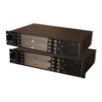
AudioCodes IPmedia 3000 Installation Manual (90 pages)
with TP-6310 or TP-8410 Blade, with IPM-6310 Blade
Brand:
AudioCodes
| Category:
Gateway
| Size: 3 MB
Table of Contents
Table of Contents
3
1 Introduction
11
2 Physical Description
13
Components
13
Table 2-1: Number and Type of Blades Per Device
13
Front and Rear Panels
14
Figure 2-1: Front Panel Main Components
14
Figure 2-2: Rear Panel Main Components
15
Table 2-2: Front-Panel Component Descriptions
15
Table 2-3: Rear-Panel Component Descriptions
15
Chassis
16
Dimensions
16
Card Cage and Slot Assignment
16
Table 2-4: Chassis Dimensions
16
Table 2-5: Blade and RTM Chassis Slot Assignment
17
Figure 2-3: Front- and Rear-Panel Slot Assignment for Ipmedia 3000 and Mediant 3000 Simplex with
18
Figure 2-4: Front- and Rear-Panel Slot Assignment for Mediant 3000 HA with 6310 Blades
19
Figure 2-5: Front- and Rear-Panel Slot Assignment for Mediant 3000 Simplex with 8410 Blades
20
Figure 2-6: Front- and Rear-Panel Slot Assignment for Mediant 3000 HA with 8410 Blades
20
Alarm Leds and ACO Button
21
Figure 2-7: Fan Tray Unit with Alarm Leds and ACO Button
21
Table 2-6: Fan Tray Module's Front-Panel Alarm Leds Description
21
6310 Blade
22
Figure 2-8: 6310 Blade
22
Figure 2-9: Components Location on 6310 Blade
23
Leds
24
Table 2-7: Blade Status Leds Description
24
Table 2-8: Gigabit Ethernet (GBE) Leds Description
24
Table 2-10: Cpci Leds Description
25
Table 2-9: PSTN Leds (STM-1/OC-3 or T3 Interface) Description
25
Figure 2-10: RTM-6310 Ports Location
26
RTM-6310 Rear Transition Module
26
Table 2-11: RTM-6310 Interface Ports Description
26
Figure 2-11: RTM-6310 Redundant Rear Transition Module
27
RTM-6310 Redundancy Rear Transition Module
27
8410 Blade
28
Figure 2-12: 8410 Blade Component Description
28
Leds
29
Table 2-12: Blade Status Leds Description
29
Table 2-13: Ethernet Leds Description
29
Table 2-14: PSTN E1/T1/J1 Leds Description
29
Figure 2-13: LED Array Display on 8410 Vop Blade
30
LED Array Display
30
Table 2-15: Cpci Leds Description
30
RTM-8410 Rear Transition Module
31
Table 2-16: Type and Quantity of RTM-8410 Per E1/T1 Span Configuration
31
Figure 2-14: RTM-8410 for 16 Spans (Single SCSI Port)
32
Figure 2-15: RTM-8410 Redundant for 16 Spans in Slot 4 (Only for Mediant 3000 HA)
32
RTM-8410 for 16-Span Configuration
32
Figure 2-16: Two RTM-8410'S for 84 Spans (Two SCSI Ports) in Slots 2 and 4
33
RTM-8410 for Scalable Span Configuration
33
Alarm, Status and Synchronization Blade
34
Figure 2-18: Alarm, Status and Synchronization Blade (SA/M3K)
34
Table 2-17: SA/M3K Blade Leds Description
35
Chassis Cooling System
36
Figure 2-19: Fan Tray Module
36
Figure 2-20: Air Baffle Panel for Unoccupied Front-Panel Slots
36
Power Supply
37
AC Power System
38
AC Power Entry Modules
38
Table 2-18: AC Power Supply Specifications
38
Figure 2-21: PEM/AC/3K Power Entry Module
39
Table 2-19: PEM AC Power Front View Component Descriptions
39
AC Power Supply Modules
40
Figure 2-22: PS/AC/3K Power Supply Module
40
Table 2-20: PS/AC/3K Technical Specifications
40
DC Power System
41
Table 2-21: PS AC Power Supply Leds Description
41
Table 2-22: DC Power Supply Specifications
41
DC Power Entry Module
42
Figure 2-23: Power Entry Module (PEM)
42
Table 2-23: PEM Front View Component Descriptions
42
DC Power Supply Modules
44
Figure 2-24: PS/DC/3K Power Supply Module
44
Table 2-24: PS/DC/3K Technical Specifications
44
Table 2-25: PS Leds Description
44
3 Installation
45
Unpacking and Checking Package Contents
45
Mounting the Device
45
Figure 3-1: Chassis Mounted in 19-Inch Rack
46
Cabling
47
Earthing (Grounding) the Chassis
48
Cabling RTM-6310 Interfaces
48
Connecting STM-1/OC-3 PSTN Interfaces
49
Connecting T3 PSTN Interfaces
50
Figure 3-2: Cabling the PSTN Fiber Optic Interface
50
Connecting Gbe Interfaces to IP Network
51
Figure 3-3: Mini SMB-To-BNC Adaptor Cable (Separate Customer Order)
51
Figure 3-4: Cabling the SMB Connector Pair for T3 Interface
51
Figure 3-5: RJ-45 LAN Ethernet Network Port and Connector
52
Figure 3-6: Cabling for LAN Redundancy in Mediant 3000 HA System Only
52
Table 3-1: RJ-45 Connector Pinouts for Gigabit Ethernet Interface
52
Cabling RTM-8410 Interfaces
53
Connecting E1/T1 PSTN Interfaces
53
Table 3-2: Trunk Numbers for 68- and 100-Pin SCSI Connectors Per Supported Span Configuration
53
Figure 3-7: 100-Pin SCSI Patch Cable Adapter for 16 Spans (Not Supplied)
54
Table 3-3: Recommended Cable Terminations for 68-Pin and 100-Pin SCSI Connectors
54
Figure 3-8: Patch Cable for 42 Spans
55
Figure 3-9: 100-Pin SCSI Female Connector on RTM-8410 Blade
56
Table 3-4: E1/T1 Connections 1 - 25 on the 100-Pin SCSI Connector
56
Figure 3-10: 68-Pin SCSI Female Connector on RTM-8410 Blade
57
Table 3-5: E1/T1 Connections 26 - 42 on the 68-Pin SCSI Connector
57
Connecting Ethernet Interfaces to OAMP and Control IP Networks
58
Figure 3-11: Cabling PEM Ethernet Ports to Control and OAM Networks
58
Figure 3-12: RJ-45 Connector Pinouts
58
Connecting Gbe Interfaces to IP Network
59
Table 3-6: RJ-45 Connector Pinouts
59
Cabling PEM for BITS Mode
60
Figure 3-13: RJ-45 LAN Ethernet Network Port and Connector
60
Connecting the Alarm Terminal Block Closures
61
Figure 3-14: Cabling BITS Trunk Sources on PEM
61
Figure 3-15: Spring-Cage Alarm Terminal Block Pins
61
Connecting the RS-232 Port to a PC
62
Figure 3-16: Normal Logic Alarm Connection (Redundancy Scheme)
62
Figure 3-17: RS-232 Cable Adapter (Supplied)
62
Table 3-7: Alarm Terminal Block Pin Details
62
Connecting Power
63
Connecting to the AC Power Supply
63
Connecting to the DC Power Supply
64
Figure 3-18: Connecting AC Power Cord
64
Figure 3-19: Power Feed Cable Terminated with Crimp-Connection Type DC Terminal Block
65
Figure 3-20: DC Power Connector with and Without Screw-Type Terminal Block Connector
66
4 Maintenance and Repair
67
Ensuring ESD Protection
67
Replacing Blades/Rtms
68
Figure 4-1: Ejector / Injector Latches on Blades/Rtms
68
Figure 4-2: Mediant 3000 Page
69
Figure 4-3: Blank Panel for Unoccupied Slots
71
Replacing the Power Supply Module
72
Replacing the Power Entry Module
72
Replacing the Fan Tray Module
73
Replacing the Air Filter
73
Figure 4-4: Removing the Air Filter
74
Figure 4-5: Air Filter
74
Replacing 155-Mbps Optical SFP Transceiver Modules (Only 6310 Blades)
75
Figure 4-6: Inserting Protective Dust Cover into SFP Cage
75
Figure 4-7: Unlocking the SFP Module
76
Figure 4-8: Inserting SFP Module into the Blade's SFP Cage
76
5 Assigning an IP Address
77
Assigning an IP Address to Ipmedia 3000 and Media 3000 Simplex
77
Table 5-1: Default IP Addresses
77
Assigning an IP Address Using HTTP
78
Figure 5-1: Enter Network Password Screen
78
Assigning an IP Address Using Bootp
79
Assigning an IP Address Using the CLI
80
Figure 5-2: Bootp Client Configuration Screen
80
Assigning an IP Address for Mediant 3000 HA
82
Using the Web Interface
82
Figure 5-3: Clients for each Blade Added in Bootp Utility
83
Figure 5-4: Multiple Interface Table Page
84
Figure 5-5: Maintenance Actions Page
84
Using the EMS
85
Figure 5-6: Adding a Region in EMS for Mediant 3000 HA
86
Figure 5-7: Defining IP Address of Mediant 3000
86
Figure 5-8: Defining Global IP Address in EMS
87
6 Restoring to Factory Defaults
89
Restoring Defaults Using the Reset Button
89
Restoring Factory Defaults Using CLI
89
Advertisement
Advertisement
Related Products
AudioCodes i Series
AudioCodes IPmedia 3000 Series
AudioCodes IPmedia 2000
AudioCodes IPM-8410
AudioCodes IPM-6310
AudioCodes Commander MP264DB
AudioCodes E-SBC
AudioCodes Gateway & Session Border Controller Series
AudioCodes GW & E-SBC Series
AudioCodes LTRT-10206
AudioCodes Categories
Gateway
IP Phone
Controller
Network Router
Conference System
More AudioCodes Manuals
Login
Sign In
OR
Sign in with Facebook
Sign in with Google
Upload manual
Upload from disk
Upload from URL