Sign In
Upload
Manuals
Brands
Atmel Manuals
Controller
XMEGA B
Atmel XMEGA B Manuals
Manuals and User Guides for Atmel XMEGA B. We have
1
Atmel XMEGA B manual available for free PDF download: User Manual
Atmel XMEGA B User Manual (415 pages)
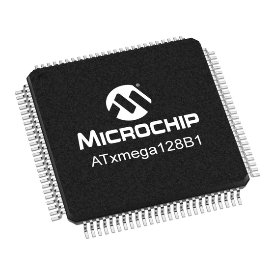
8-bit Microcontroller
Brand:
Atmel
| Category:
Controller
| Size: 6 MB
Table of Contents
1 About the Manual
2
Reading the Manual
2
Resources
2
Recommended Reading
2
2 Overview
3
3 Atmel AVR CPU
7
Features
7
Overview
7
Architectural Overview
7
ALU - Arithmetic Logic Unit
8
Program Flow
9
Instruction Execution Timing
9
Status Register
10
Stack and Stack Pointer
10
Register File
10
RAMP and Extended Indirect Registers
12
Accessing 16-Bit Registers
13
Configuration Change Protection
13
Fuse Lock
14
Register Descriptions
15
Register Summary
19
4 Memories
20
Features
20
Overview
20
Flash Program Memory
20
Fuses and Lockbits
22
Data Memory
22
Internal SRAM
23
Eeprom
23
I/O Memory
23
Data Memory and Bus Arbitration
23
Memory Timing
24
Device ID and Revision
24
JTAG Disable
25
I/O Memory Protection
25
Register Description - NVM Controller
26
Register Descriptions - Fuses and Lock Bits
30
Register Description - Production Signature Row
36
Register Description - General Purpose I/O Memory
42
Register Descriptions - MCU Control
42
Register Summary - NVM Controller
46
Register Summary - Fuses and Lock Bits
46
Register Summary - Production Signature Row
47
Register Summary - General Purpose I/O Registers
48
Register Summary - MCU Control
48
Interrupt Vector Summary - NVM Controller
48
5 DMAC - Direct Memory Access Controller
49
Features
49
Overview
49
DMA Transaction
50
Transfer Triggers
51
Addressing
51
Priority between Channels
51
Double Buffering
51
Transfer Buffers
51
Error Detection
52
Software Reset
52
Protection
52
Interrupts
52
Register Description - DMA Controller
53
Register Description - DMA Channel
55
Register Summary - DMA Controller
64
Register Summary - DMA Channel
64
DMA Interrupt Vector Summary
64
6 Event System
65
Features
65
Overview
65
Events
66
Event Routing Network
68
Event Timing
69
Filtering
70
Quadrature Decoder
70
Register Description
72
Register Summary
76
7 System Clock and Clock Options
77
Features
77
Overview
77
Clock Distribution
79
Clock Sources
79
System Clock Selection and Prescalers
81
PLL with 1X-31X Multiplication Factor
82
DFLL 2Mhz and DFLL 32Mhz
82
PLL and External Clock Source Failure Monitor
84
Register Description - Clock
85
Register Description - Oscillator
89
Register Description - DFLL32M/DFLL2M
93
Register Summary - Clock
96
Register Summary - Oscillator
96
Register Summary - DFLL32M/DFLL2M
96
Oscillator Failure Interrupt Vector Summary
96
8 Power Management and Sleep Modes
97
Features
97
Overview
97
Sleep Modes
97
Power Reduction Registers
99
Minimizing Power Consumption
99
Register Description - Sleep
101
Register Description - Power Reduction
101
Register Summary - Sleep
104
Register Summary - Power Reduction
104
9 Reset System
105
Features
105
Overview
105
Reset Sequence
106
Reset Sources
107
Register Description
111
Register Summary
112
10 WDT - Watchdog Timer
113
Features
113
Overview
113
Normal Mode Operation
113
Window Mode Operation
114
Watchdog Timer Clock
114
Configuration Protection and Lock
114
Registers Description
115
Register Summary
117
11 Interrupts and Programmable Multilevel Interrupt Controller
118
Features
118
Overview
118
Operation
118
Interrupts
119
Interrupt Level
121
Interrupt Priority
121
Interrupt Vector Locations
123
Register Description
124
Register Summary
125
12 I/O Ports
126
Features
126
Overview
126
I/O Pin Use and Configuration
127
Reading the Pin Value
131
Input Sense Configuration
132
Port Interrupt
132
Port Event
133
Alternate Port Functions
134
Clock and Event Output
135
Multi-Pin Configuration
135
Virtual Ports
135
Register Descriptions - Ports
136
Register Descriptions - Port Configuration
143
Register Descriptions - Virtual Port
147
Register Summary - Ports
149
Register Summary - Port Configuration
149
Register Summary - Virtual Ports
149
Interrupt Vector Summary - Ports
150
13 TC0/1 - 16-Bit Timer/Counter Type 0 and 1
151
Features
151
Overview
151
Block Diagram
153
Clock and Event Sources
154
Double Buffering
154
Counter Operation
155
Capture Channel
157
Compare Channel
160
Interrupts and Events
163
DMA Support
163
Timer/Counter Commands
163
Register Description
164
Register Summary
175
Interrupt Vector Summary
175
14 TC2 - 16-Bit Timer/Counter Type 2
176
Features
176
Overview
176
Block Diagram
177
Clock Sources
177
Counter Operation
178
Compare Channel
178
Interrupts and Events
180
DMA Support
180
Timer/Counter Commands
180
Register Description
181
Register Summary
187
Interrupt Vector Summary
187
15 Awex - Advanced Waveform Extension
188
Features
188
Overview
188
Port Override
189
Dead-Time Insertion
190
Pattern Generation
191
Fault Protection
192
Register Description
194
Register Summary
198
16 Hi-Res - High-Resolution Extension
199
Features
199
Overview
199
Register Description
200
Register Summary
200
17 RTC - Real-Time Counter
201
Features
201
Overview
201
Register Descriptions
203
Register Summary
208
Interrupt Vector Summary
208
18 USB - Universal Serial Bus Interface
209
Features
209
Overview
209
Operation
210
SRAM Memory Mapping
214
Clock Generation
214
Ping-Pong Operation
215
Multipacket Transfers
216
Auto Zero Length Packet
217
Transaction Complete FIFO
217
Interrupts and Events
218
VBUS Detection
219
On-Chip Debug
220
Register Description - USB
221
Register Description - USB Endpoint
228
Register Description - Frame
233
Register Summary - USB Module
234
Register Summary - USB Endpoint
234
Register Summary - Frame
234
USB Interrupt Vector Summary
234
19 TWI - Two-Wire Interface
235
Features
235
Overview
235
General TWI Bus Concepts
236
TWI Bus State Logic
241
TWI Master Operation
242
TWI Slave Operation
244
Enabling External Driver Interface
245
Register Description - TWI
246
Register Description - TWI Master
247
Register Description - TWI Slave
252
Register Summary - TWI
257
Register Summary - TWI Master
257
Register Summary - TWI Slave
257
Interrupt Vector Summary
257
20 SPI - Serial Peripheral Interface
258
Features
258
Overview
258
Master Mode
259
Slave Mode
259
Data Modes
259
DMA Support
260
Register Description
261
Register Summary
263
Interrupt Vector Summary
263
21 Usart
264
Features
264
Overview
264
Clock Generation
265
Frame Formats
269
USART Initialization
270
Data Transmission - the USART Transmitter
270
Data Reception - the USART Receiver
270
Asynchronous Data Reception
271
Fractional Baud Rate Generation
274
USART in Master SPI Mode
276
USART SPI Vs. SPI
276
Multiprocessor Communication Mode
277
IRCOM Mode of Operation
278
DMA Support
278
Register Description
279
Register Summary
284
Interrupt Vector Summary
284
22 IRCOM - IR Communication Module
285
Features
285
Overview
285
Registers Description
287
Register Summary
288
23 AES and des Crypto Engines
289
Features
289
Overview
289
DES Instruction
289
AES Crypto Module
290
Register Description - AES
293
Register Summary - AES
296
Interrupt Vector Summary
296
24 CRC - Cyclic Redundancy Check Generator
297
Features
297
Overview
297
Operation
298
CRC on Flash Memory
298
CRC on DMA Data
298
CRC Using the I/O Interface
299
Register Description
300
Register Summary
302
25 LCD - Liquid Crystal Display
303
Features
303
Overview
303
Block Diagram
305
Mode of Operation
306
Register Description - LCD
312
Register Summary - LCD
324
Interrupt Vector Summary
324
26 ADC - Analog-To-Digital Converter
325
Features
325
Overview
325
Input Sources
326
Sampling Time Control
329
Voltage Reference Selection
329
Conversion Result
330
Compare Function
331
Starting a Conversion
331
ADC Clock and Conversion Timing
331
ADC Input Model
334
DMA Transfer
335
Interrupts and Events
335
Calibration
335
Synchronous Sampling
335
Register Description - ADC
336
Register Description - ADC Channel
342
Register Summary - ADC
349
Register Summary - ADC Channel
349
Interrupt Vector Summary
349
27 AC - Analog Comparator
350
Features
350
Overview
350
Input Sources
351
Signal Compare
351
Interrupts and Events
351
Window Mode
352
Input Hysteresis
352
Register Description
353
Register Summary
358
Interrupt Vector Summary
358
28 IEEE 1149.1 JTAG Boundary Scan Interface
359
Features
359
Overview
359
TAP - Test Access Port
359
JTAG Instructions
361
Boundary Scan Chain
362
Data Registers
363
29 Program and Debug Interface
366
Features
366
Overview
366
PDI Physical
367
PDI Controller
371
Register Description - PDI Instruction and Addressing Registers
373
Register Description - PDI Control and Status Registers
375
Register Summary
376
30 Memory Programming
377
Features
377
Overview
377
NVM Controller
377
NVM Commands
378
NVM Controller Busy Status
378
Flash and EEPROM
379
Flash and EEPROM Programming Sequences
379
Protection of NVM
380
Preventing NVM Corruption
380
CRC Functionality
381
Self-Programming and Boot Loader Support
381
External Programming
390
Register Description
395
Register Summary
395
31 Peripheral Module Address Map
396
32 Instruction Set Summary
397
33 Datasheet Revision History
402
Advertisement
Advertisement
Related Products
Atmel AVR XMEGA AU series
Atmel AVR1925 XMEGA-C3 Xplained
Atmel AVR XMEGA-A3BU
Atmel AVR XMEGA E
Atmel AVR XMEGA D Series
Atmel AT43301
Atmel AT43USB324
Atmel AT43USB325
Atmel AT89C51ED2
Atmel AT91 ARM Series
Atmel Categories
Microcontrollers
Motherboard
Computer Hardware
Controller
Accessories
More Atmel Manuals
Login
Sign In
OR
Sign in with Facebook
Sign in with Google
Upload manual
Upload from disk
Upload from URL