Sign In
Upload
Manuals
Brands
arcelik Manuals
Washer
Beko B13
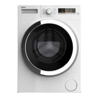
arcelik Beko B13 Manuals
Manuals and User Guides for arcelik Beko B13. We have
2
arcelik Beko B13 manuals available for free PDF download: Service Handbook
arcelik Beko B13 Service Handbook (186 pages)
Brand:
arcelik
| Category:
Washer
| Size: 8 MB
Table of Contents
Cover
2
2 Contents
2
Table of Contents
2
3 Safety Warnings
6
General Safety
6
Electrical Safety
6
Intended Use
7
Children's Safety
7
Compliance with Eee Directive
7
Package Information
8
Disposing of Waste Product
8
Points to be Considered During Service
8
4 Technical Specifications
10
Product Definition
10
Outer Dimensions
10
Package
10
Weight
10
General Technical Values
10
Supply Cable
10
Motor
11
Pump
11
Heater
11
Water Inlet
11
Body
11
Drum
11
Drum
12
Shock Absorber System
12
Pump Control
12
5 Product Installation / Installation Rules / Settings
13
Appropriate Place for Installation
13
Removing Packaging Reinforcement
13
Removing the Transportation Locks
14
Connecting to Water Supply
15
Connecting to Water Drain
16
Adjusting the Feet
17
Electrical Connection
18
Transportation of the Product
18
6 Product Use and Byproducts
19
Preparation
19
Sorting the Laundry
19
Preparing Laundry for Washing
20
Things to be Done for Energy Saving
20
Initial Use
20
Correct Load Capacity
21
Loading the Laundry
22
Using Detergent and Softener
22
Control Panel
25
Display Symbols
25
Preparing the Machine
26
Programme Selection
26
Main Programmes
27
Additional Programmes
29
Special Programmes
30
Temperature Selection
31
Spin Speed Selection
31
Programme and Consumption Table
33
Auxiliary Function Selection
34
End Time
36
Starting the Programme
36
Loading Door Lock
37
Changing the Selections after a Programme Has Started
37
Child Lock
38
Cancelling the Programme
39
End of Programme
39
Adjusting the Volume Level
39
7 Maintenance and Cleaning
40
Cleaning the Detergent Drawer
40
Cleaning the Loading Door and the Drum
40
Cleaning the Body and Control Panel
41
Cleaning the Water Intake Filters
41
Draining Remaining Water and Cleaning the Pump Filter
42
8 General Operation Principle
45
Water Intake Profile
45
Heating Profile
47
Antifoaming Profile
48
Foam Detection and Defoaming Algorithm
49
Programme Streamlines
50
9 Component Operation Principles
73
Electronic Card Assembly
73
Touchkey Technique
73
Picture 9.1 Electronic Card Assembly
73
Picture 9.2 Panel
73
Picture 9.3 Electronic Card (Spring)
74
Picture 9.4 Panel Rear Detail
74
Water Intake Valve (with Water Counter)
75
Steam Input Valve
75
Picture 9.6 Water Intake Valve
75
Picture 9.7 Steam Input Valve
75
Steam Generator
76
Operation Principle
76
Picture 9.8 Steam Generator
76
Water Counter (Hot Water Valve Model)
79
Picture 9.11 Correct Mounting of Water Counter (Hot Water Valve Model)
79
Picture 9.12 Water Counter
79
Water Level Sensor
80
Parasite Filter
80
Picture 9.13 Water Level Sensor
80
Picture 9.14 Parasite Filter
80
Input Impedance Coil
81
Wash Motor
81
Askoll Motor
81
Picture 9.15 Input Impedance Coil
81
Picture 9.16 Askoll Motor (Askoll Motor Ve Motor Card)(Integrated)
81
Atlas Motor
82
UM/DC/AC Motor
83
Safety Keys (Door Lock)
83
Picture 9.19 Safety Key
83
Heater
84
Ntc
84
Picture 9.20 Heater
84
Picture 9.21 Ntc
84
Drain Pump
85
Jet System Pump
85
Picture 9.22 Drain Pump
85
Ntc Values
85
Aquastop (Overflow Key)
86
Picture 9.23 Jet System Pump
86
Picture 9.24 Aquastop
86
10 Service Function Test
87
Step Nr. 0: Entering the Service Programme
87
Step Nr. 1: Error Code Control
87
Step Nr. 2: Software Version Check
87
Step Nr. 3: Indicator Control
88
Step Nr. 4: Water Level Sensor / NTC / Mains Voltage / Motor Clockwise Control
88
Step Nr. 5: Motor Counterclockwise Washing Control
89
Step Nr. 6: Machine Spin Speed (Max. Speed) Control
89
Step Nr. 7: Steam Valve Control (if There Is no Steam Valve, this Step will be Skipped.)
89
Step Nr. 8: Steam Heater Control (ID There Is no Steam Heater, Step will be Skipped.)
90
Step Nr. 9: Prewash Valve and Porewash Valve Flowmeter Control
91
Step Nr. 10: Main Wash Valve and Main Wash Valve Flowmeter Control
91
Step Nr. 11: Detergent Box Control and Detergent Box Siphon Control
92
Step Nr. 12: Hot Water Valve Control
92
I F Not , Next Step will be Switched to )
92
Explanation
92
Step Nr. 13: Heater Control
93
Step Nr. 14: Pump Control
94
Step Nr. 15: Jet Pump Control
94
Step Nr. 16: Displaying of the Errors Occurred in the Service Mode
95
Step Nr. 17: How Many Times the Service Mode was Completed Without any Problem
96
11 Failure / Error Codes
97
12 Failure Flow / Troubleshooting Diagrams
98
Electronic Card Sockets
98
Machine Does Not Operate
99
Error Codes and Likely Customer Complaints
100
Replace the Valve . Try Again
109
E9 - E10
110
E11_1
111
E11_2
112
E11_3
113
E11_4
114
E12
115
E13
116
E15
117
E17
118
E18
119
E28
120
E29
121
Programme Selection Key Does Not Select
122
Machine Is Blowing the Fuse
123
It Takes Water in from the Wrong Compartment
124
Machine Takes in too Much Water
125
Steam Generator Does Not Function
126
13 Electrical Circuit / Connection / E-Card Diagrams
128
14 Equipment / Aparatus List to be Used for Component Attachment - Detachment
132
Schock Absorber Pin Nailing Apparatus
132
Picture 14.2
132
Picture 14.3
132
Picture 14.4
133
Picture 14.5
133
Picture 14.6
133
Picture 14.7
134
Picture 14.8
134
Picture 14.9
134
15 Component Attachment - Detachment
135
Upper Table Attachment / Detachment
135
Attachment
135
Picture 15.1 General View
135
Picture 15.2 Upper Table Attachment - 1
135
Picture 15.3 Upper Table Attachment - 2
135
Detachment
136
Picture 15.4 Upper Table Attachment - 3
136
Picture 15.5 Upper Table Attachment - 4
136
Picture 15.6 Upper Table Detachment - 1
136
Picture 15.7 Upper Table Detachment - 2
136
Panel Attachment / Detachment
137
Attachment
137
Picture 15.8 Upper Table Detachment - 3
137
Picture 15.9 Upper Table Detachment - 4
137
Picture 15.10 Panel Attachment -1
137
Picture 15.11 Panel Attachment -2
137
Detachment
138
Picture 15.12 Panel Detachment -1
138
Picture 15.13 Panel Detachment 2
138
Picture 15.14
138
Picture 15.1 Panel Detachment 4
138
Picture 15.1 Panel Detachment 5
139
Picture 15.17 Panel Detachment 6
139
Picture 15.18 Panel Detachment - 7
139
Picture 15.19 Panel Detachment - 8
139
Picture 15.20 Card Socket Connections - 1
140
Cover Group Attachment / Detachment
141
Attachment
141
Picture 15.22 Front Door Detachment / Attachment
141
Pump Cover Attachment / Detachment
142
Front Wall Attachment / Detachment
142
Picture 15.26 Front Wall Detachment / Attachment
142
Picture 15.27 Front Wall Detachment / Attachment
142
Picture 15.28 Front Wall Detachment / Attachment
143
Detergent Box Attachment / Detachment
144
Attachment
144
Picture 15.32
144
Picture 15.33 Detergent Box Attachment
144
Picture 15.34
144
Picture 15.35
144
Detachment
145
Single Valve Attachment / Detachment
145
Picture 15.363 Detergent Box Detachment
145
Picture 15.37
145
Picture 15.39
145
Picture 15.40 Valves
145
Triple Valve Attachment / Detachment
146
Steam Generator and Parts' Attachment / Detachment
146
Steam Generator Detachment
146
Picture 15.41 Steam Generator Connection
146
Picture 15.42
146
Picture 15.43
147
Picture 15.44 Steam Generator Hook
147
Picture 15.45 Removal of Steam Generator
148
Picture 15.46 Steam Generator Electrical Connection
148
Picture 15.47
149
Picture 15.48
149
Picture 15.49
149
Picture 15.50 Steam Generator Hose Detachment
150
Picture 15.51 Hose Attachment
150
Picture 15.52
151
Picture 15.53
151
Picture 15.54
152
Picture 15.55
152
Picture 15.56 Placing the Steam Generator in the Machine
152
Picture 15.57
153
Picture 15.58
153
Steam Generator Bracket Attachment / Detachment
154
Picture 15.59
154
Picture 15.60
154
Picture 15.61
154
Picture 15.62 Steam Generator Bracket Detachment
155
Picture 15.63 Steam Generator Bracket Attachment
155
Picture 15.64
156
Picture 15.65
156
Picture 15.66
156
Steam Hose Attachment / Detachment
157
Picture 15.67
157
Picture 15.68
157
Picture 15.69
157
Picture 15.70 Steam Hose Detachment
158
Picture 15.71 Steam Hose Attachment
158
Steam Generator Water Hose Attachment / Detachment
159
Picture 15.72
159
Picture 15.73
159
Picture 15.74
159
Picture 15.75
160
Picture 15.76
160
Picture 15.77
160
Picture 15.78
160
Water Counter Attachment / Detachment
161
Picture 15.79
161
Picture 15.80
161
Picture 15.81 Water Counter Attachment
161
Water Level Sensor Attachment / Detachment
162
Parasite Filter Attachment/Detachment
162
Supply Cable Attachment / Detachment
162
Picture 15.82 Water Level Sensor Attachment
162
Picture 15.83 Supply Cable Attachment
162
Impedance Coil Attachment/Detachment
163
Picture 15.84 Impedance Coil
163
Picture 15.85 Step 1
163
Picture 15.86 Step 2
163
Picture 15.87 Step 3
164
Picture 15.88 Step 4
164
Picture 15.89 Step 5
164
Motor
165
2.Atlas Motor
165
Askoll Motor
165
Blac External Rotor Motor
165
Picture 15.90 Motor
165
Picture 15.91 Motor
165
Um/DC/Ac
166
Polyv Belt Attachment
166
Picture 15.92 Motor
166
Picture 15.93 Belt Attachment - 1
166
Picture 15.943 Belt Attachment - 2
166
Shock Absorber and Shock Absorber Pin Attachment / Detachment
167
Picture 15.95 Belt Attachment - 3
167
Picture 15.963 Belt Attachment - 4
167
Picture 15.97 Shock Absorber Pin
167
Picture 15.98
167
Shock Absorber Attachment / Detachment
168
Upper Balance Weight Attachment / Detachment
168
Picture 15.99 Shock Absorber
168
Picture 15.101 Upper Balance Weight
168
Lower Balance Weight Attachment / Detachment
169
Drain Pump Attachment / Detachment
169
Picture 15.102 Lower Balance Weight
169
Picture 15.103 Drain Pump
169
Jet System Assembly Attachment / Detachment
170
Water Input Hose Attachment / Detachment
170
Buoy Attachment / Detachment (Aquastop)
171
Drain Hose Attachment / Detachment
171
16 Drain Siphon Cut-Off System Integrated Products
171
17 Exploded Drawings
175
Drive Assembly
175
Control Group
176
Double Water System Group
177
Single Water System Group
178
Front Cover Assembly
179
Body Assembly
180
Isolation Group
181
Visual Group
182
Front Wall and Kickplate Assembly
183
Front Wall and Kickplate Assembly
184
18 Part List
184
Advertisement
arcelik Beko B13 Service Handbook (111 pages)
Brand:
arcelik
| Category:
Washer
| Size: 5 MB
Table of Contents
Door
1
Table of Contents
2
Door
2
Contents
2
Security Warnings
5
General Security
5
Electrical Safety
5
Product Safety
5
Intended Use
6
Child Safety
6
Compliance to Rohs Directive
6
Packaging Information
7
Disposal of Waste Product
7
Points to Consider During Service
7
Product Installation / Installation Rules / Settings
9
Correct Place for Installation
9
Removing the Package Support
10
Removing the Transport Safety Bolts
10
List of Figures and Pictures
10
Fi̇gure 4.2
10
Fi̇gure 4.3
10
Connection to the Supply Water
11
Fi̇gure 4.4
11
Fi̇gure 4.5
11
Connection to the Water Drain
12
Fi̇gure 4.6
12
Fi̇gure 4.7
12
Adjustment of Legs
13
Fi̇gure 4.8
13
Fi̇gure 4.9
13
Electrical Connection
14
Transportation of the Product
14
Fi̇gure 4.10
14
Fi̇gure 4.11
14
Use of Product and Byproducts
16
Preparation
16
Sorting the Laundry
16
Fi̇gure 5.1 Washi̇ng Symbols
16
Preparation of the Garments to be Washed
17
Fi̇gure 5.2
17
Things to Do for Energy Saving
18
Correct Load Capacity
18
Fi̇gure 5.3 Laundry Wei̇ghts
18
Laundry Loading
19
Use of Detergent and Softener
19
Fi̇gure 5.4 Compartments of the Detergent Dİspenser
19
Figure 4.5 Use of Liquid Detergent Container
21
First Use
22
Fi̇gure 5.6 Cleani̇ng the Bellows
22
Control Panel
23
Figure 5.7 Control Panel
23
Preparing the Machine
24
Figure 5.8 Control Panel
24
Program Selection and Tips for Correct Washing
25
Main Programs
26
Additional Programs
26
Special Programs
27
Temperature Selection
27
Auxiliary Function Selection
28
Starting the Program
30
Child Lock
30
Progress of the Program
31
Lock of the Loading Door
31
Changing the Selections after the Program Started
31
Cancellation of Program
32
Program End
32
There Is a "Standby Mode" in Your Machine
32
Maintenance and Cleaning
33
Cleaning the Detergent Dispenser
33
Figure 6.1 Cleaning the Detergent Compartment
33
Cleaning the Loading Door and the Drum
34
Cleaning the Body and Control Panel
34
Fi̇gure 6.2 Cleani̇ng the Bellows
34
Cleaning the Water Inlet Filters
35
Draining the Remaining Water and Cleaning the Pump Filter
35
Fi̇gure 6.3
35
Fi̇gure 6.4 Cleani̇ng the Fi̇lter - 1
36
Fi̇gure 6.6 Cleani̇ng the Pump - 2
36
Fi̇gure 6.6 Cleani̇ng the Pump Fi̇lter - 3
37
Fi̇gure 6.7 Cleani̇ng the Pump Fi̇lter - 4
37
Fi̇gure 6.7 Cleani̇ng the Pump Fi̇lter - 5
37
General Operating Principle
39
Water Intake Profile
39
Figure 7.1 Water Intake Graphic
39
Figure 7.2 Top Closure Algorithm
40
Heating Profile
41
Anti-Foaming Profile
41
Fi̇gure 7.3 Graphi̇C for Heati̇ng Wi̇th Hysteresi̇s
41
Foam Detecting and Extinguishing Algorithm
42
Programme Flows
43
Figure 8.4 Programme Flow Example
44
Component Working Principles
48
Electronic Control and Visual Card
48
Pi̇cture 8.1 Conrol Karti
48
Safety Switch (Door Lock)
49
Motor
49
Picture 8.2 Safety Switch
49
Heater
50
Valve
50
Drain Pump
50
Picture 8.3. Motor
50
Picture 8.4 Heater
50
Picture 8.5 Drain Pump
50
Ntc
51
Water Level Sensor
51
Picture 8.6 NTC
51
Ntc Values
51
Picture 8.7 Water Level Sensor
52
Service Function Test
53
B13 B7S B7Sled Failure Flow Diagram
57
List of Equipment/Apparatus to be Used in Component Assembly / Disassembly
80
Shock Absorber Pin Punching Apparatus
80
Picture 11.1 Shock Absorber Pin Punching Apparatus
80
Pi̇cture 11.2
80
Pi̇cture 11.8
82
Pi̇cture 11.9
82
Component Assembly / Disassembly
83
Upper Table Assembly / Disassembly
83
Picture 12.1 General Appearance
83
Picture 12.2 Upper Table Disassembly/Assembly
83
Front Door Group Assembly/Disassembly
84
Picture 12.5 Front Door Disassembly /Assembly
84
Exterior Door
85
Picture 12.7 Front Door Disassembly /Assembly
85
Pi̇cture 12.8
85
Hinge
86
Handle Cover
86
Picture 12.10 Hinge
86
Picture 12.11 Assembly/Disassembly of Handle Cover
86
Handle
87
Lock Hook- Spring
87
Pi̇cture 12.12
87
Pi̇cture 12.13
87
Figure 12.14 Handle
87
Decorative Cover
88
Glass
88
Pump Cover Assembly/Disassembly
88
Picture 12.15 Decorative Cover
88
Pi̇cture 12.16
88
Front Wall Disassembly/Assembly
89
Picture 12.18 Front Wall Disassembly / Assembly
89
Picture 12.19 Front Wall Disassembly / Assembly
89
Dispenser Panel
90
Picture 12.20 Front Wall Disassembly / Assembly
90
Panel
91
Picture 12.23 Disassembly/Assembly of Detergent Dispenser
91
Picture 12.24 Panel Disassembly/Assembly
91
Picture 12.25 Panel Disassembly/Assembly
91
Protective Foil
92
Picture 12.27 Panel Disassembly/Assembly
92
Reflector
93
Program Control Card
93
Picture 12.29 Reflector Disassembly/Assembly
93
Picture 12.30 Control Card Disassembly/Assembly
93
Picture 12.31 Control Card Disassembly/Assembly
93
Parasite Filter
94
Picture 12.32 Control Card Disassembly/Assembly
94
Picture 12.33 Disassembly/Assembly of Parasite Filter
94
Detergent Compartment Connection Group
95
Single Valve
95
Two-Way Valve
95
Picture 12.34 Detergent Compartment Connection Group
95
Safety Switch
96
Heater
96
Picture 12.35 Disassembly/Assembly of Two-Way Valve
96
Picture 12.36 Disassembly/Assembly of Safety Switch
96
Pump
97
Picture 12.37 Disassembly/Assembly of Heater
97
Picture 12.38 Disassembly/Assembly of Pump
97
Drum Bellows
98
Drum Bellows Assembly
98
Water Inlet Hose
98
Picture 12.40 Disassembly/Assembly of Drum Bellows
98
Polyv Belt
99
Pulley
99
Motor
99
Picture 12.41 Disassembly/Assembly Poly V Belt
99
Picture 12.42 Disassembly/Assembly of Motor
99
Power Cable
100
Upper Counterweight
100
Lower Counterweight
100
Picture 12.43 Disassembly/Assembly of Power Cable
100
Discharge Hose
101
Power Circuit Diagram
102
Products with Built-In Draining Siphon Shut-Off System
103
Exploded Drawings
105
Body Group
105
Control Group
105
Water System
106
Visual Group
106
Front Wall Group
107
Front Door
107
Driving Group
108
Isolation Group
108
Part List
109
List of Figures and Pictures
109
Advertisement
Related Products
arcelik beko B13 GOOD PLUS
arcelik beko B7S
arcelik beko B7SLED
arcelik BEKO RETRO
arcelik BARBAROS
arcelik BT 44
arcelik BEKO COSMOS
arcelik BEKO ATLANTIC
arcelik Beko 2014 GOOD TIMER
arcelik built in oven
arcelik Categories
Refrigerator
Washer
Dishwasher
TV
Oven
More arcelik Manuals
Login
Sign In
OR
Sign in with Facebook
Sign in with Google
Upload manual
Upload from disk
Upload from URL