Sign In
Upload
Manuals
Brands
AQUALEAK Manuals
Measuring Instruments
10K
AQUALEAK 10K Manuals
Manuals and User Guides for AQUALEAK 10K. We have
1
AQUALEAK 10K manual available for free PDF download: Installation And Operation Manual
AQUALEAK 10K Installation And Operation Manual (37 pages)
Brand:
AQUALEAK
| Category:
Measuring Instruments
| Size: 1 MB
Table of Contents
Page PREFACE
2
Safety Warnings
3
List of Abbreviations
3
Table of Contents
5
CONTENTS (this List)
5
Introduction and Product Overview
5
Figures
6
Tables
6
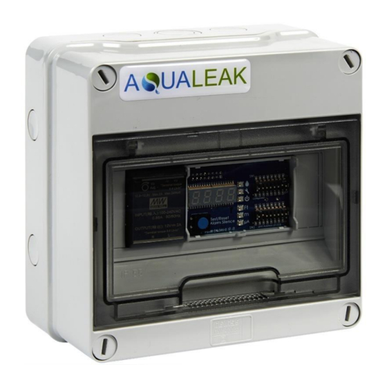
Page Figure 1 Aqualeak 10K
7
Description
8
Supervised System
8
Sensors Available
8
Distance Read Leak Detection
8
Front Panel
8
Internal Description
9
Supplied Items
9
Figure 2 Aqualeak 10K Controls and Indicators
9
Additional Items
10
Figure 3 Aqualeak 10K Interior
10
Specification
11
Page Table 1 10K Specification
11
Installation and Configuration
12
Preparation for Installation
12
Installing the Aqualeak 10K
12
Establish Physical Connections
12
Figure 4 Electrical Connections to Aqualeak 10K
13
TB1 Summary Relay (Optional)
14
TB2 Leader Cable
14
Figure 5 Relay Output Connection TB1
14
Figure 6 General DIP Switch Settings
14
Figure 7 SW1, DIP Switch 5 - Latched or Unlatched Alarms
14
TB3 and TB4: Input Power and EIA-485 Communications Ports
15
Figure 8 Cable Connection TB2
15
Figure 9 SW1, DIP Switch 6 - Display Cable Length in Feet or Meters
15
Figure 10 SW1, DIP Switch 7 - Ohms Per Foot Resistance
15
Figure 11 TB3 and TB4 Power Supply and Communications Connections
16
Figure 12 DIP Switch Settings for Communications Baud Rate
16
JMP - Termination Jumper
17
Select Alarm Options
17
Enable and Disable the Audible Alarm
17
Set the Re-Alarm Interval
17
Figure 13 DIP Switch Settings for Communications Address
17
Figure 14 DIP Switch 8, SW 1 - Audible Alarm Settings
17
Connect the Leak Detection Cable
18
Connect Lengths of Sensor Cable
18
Figure 15 DIP Switch 4, SW1 - Re-Alarm Interval
18
Figure 16 Sensor Cable
18
Secure Sensor Cable to the Floor
19
Figure 17 Example of Sensor Cable Routing in Large Data Centre
19
Applying Power to the Aqualeak 10K
20
Figure 18 Securing the Sensor Cable
20
Test the System
21
Operation
22
Front Panel Controls and Display
22
Figure 19 Aqualeak 10K Controls and Indicators
22
Table 2 Front Panel Controls and Displays
23
Manage Alarms
24
General Guidance
24
Contamination Alarm Guidelines
24
Modbus Communications
25
Modbus Implementation Basics
25
Modes of Transmission
25
Slave Address Field
25
Function Field
25
Data Field
25
Error Check (Checksum) Field
25
Exception Responses
25
Packet Communications for the Aqualeak 10K
26
Function 03: Read Output Registers
26
Table 3 Exception Codes
26
Table 4 Read Output Registers Packet Structure
26
Table 5 Output Registers
26
Function 04: Read Input Registers
28
Table 6 Read Input Registers Packet Structure
28
Table 7 Input Registers
28
RTU Framing
29
Table 8 Status Flags (Register 30001)
29
Table 9 Response Sample
29
Calibrate Sensor Cable Length Via Modbus
30
Figure 20 SW1 DIP Switch Settings for Ohms/Foot
30
Preventive Maintenance
32
Monthly Maintenance
32
Troubleshooting
33
Table10 Troubleshooting
33
Repair
34
Appendix A - Configuration Reference
35
A1. DIP Switches
35
Figure A1 General DIP Switch Settings
35
A2. SW1 DIP Switch Settings
36
Figure A2 SW1 DIP Switch Configuration Settings
36
A3. SW2 DIP Switch Settings
37
A3.1 Configure the Aqualeak 10K for Modbus Communications
37
Figure A3 SW2 DIP Switch Settings for Modbus Unit Address
37
Advertisement
Advertisement
Related Products
AQUALEAK EMS-10
AQUALEAK EMS-10X
AQUALEAK EMS-5
AQUALEAK EMS-5X
AQUALEAK EMS-OS
AQUALEAK Categories
Security Sensors
Measuring Instruments
More AQUALEAK Manuals
Login
Sign In
OR
Sign in with Facebook
Sign in with Google
Upload manual
Upload from disk
Upload from URL