Sign In
Upload
Manuals
Brands
AQUALEAK Manuals
Measuring Instruments
EMS-OS
AQUALEAK EMS-OS Manuals
Manuals and User Guides for AQUALEAK EMS-OS. We have
1
AQUALEAK EMS-OS manual available for free PDF download: Instruction Manual
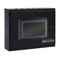
AQUALEAK EMS-OS Instruction Manual (53 pages)
Water Leak Detection System
Brand:
AQUALEAK
| Category:
Measuring Instruments
| Size: 3 MB
Table of Contents
Table of Contents
3
Safety Information
5
Intended Use
5
Statutory Obligations
5
Electrical Safety
5
Installation Safety
6
Post-Installation Safety
6
Product Overview
7
Figure 1: Aqualeak EMS-5X / 10X / os Water Leak Detection System
7
Technical Specifications
8
Table 1: EMS-5X, 10X and os Technical
8
Input-Output Connections
9
Figure 2: EMS-5X (Top) and 10X / os (Bottom) Input-Output Connections
9
Table 2: EMS-X / os Input-Output Connections
10
Multiple Zone Application Examples
11
Figure 3: EMS-5X Three-Zone Communications Room Example
11
Figure 4: EMS-OS Multiple Zone / Floor Example Using Outstations
12
Installation
13
Master Panel Installation
13
Mounting
13
Power Connection
13
Figure 5: Master Panel Electrical Power Connections
13
Relays and Sensors
14
Relay Functions and Triggers
14
Reboot Relay
14
Table 3: Relay Functions and Notes / Triggers
14
Sensor Connections
15
Figure 6: Sensor Cable Connection to Interface Board
15
Figure 7: Sensor Cable Connection Using Leader Cable (LC10C)
15
Figure 8: Sensor Cable Using LC10/LCB100 and Start of Line
16
Figure 9: Sensor Cable Using Single ESD Sensor Probe
17
Figure 10: Multiple ESD Sensor Probes to a Single Zone
18
Ancillary Devices
19
Signalling to Ancillary Device
19
12/24V Output to Ancillary Device
19
Figure 11: Connection of Master Panel for Signalling to an Ancillary Device
19
Figure 12: Using the 12/14 Output to Power an Ancillary Device
19
Output to Ancillary Device
20
Figure 13: Using the EMS to Power a 230V Ancillary Device (Normally Closed)
20
Figure 14: Using the EMS to Power a 230V Ancillary Device (Normally Open)
20
Outstations
21
Figure 15: Outstation Panel
21
Configuration
22
USB Port
22
Figure 16: Rear of EMS-5X / 10X / os Main Panel Showing USB Port
22
XML Configuration File
23
Export to USB
23
Figure 17: EMS Engineers Menu
23
EMS Settings
24
Table 4: EMS Configuration File Settings
24
Figure 18: Expanded Emssettings Folder
24
Table 5: User PIN Settings
25
User PIN Types and Numbers
25
Figure 19: Expanded Userpins and Engineerpins Folders
25
Table 6: EMS Network Settings
26
Network Settings
26
Figure 20: Expanded Networksettings Folder
26
Modbus Settings
27
Table 7: Register 0 Corresponding Replays and Register 1 Corresponding Functions
27
Table 8: Modbus Ethernet/Tcp Settings
28
Figure 21: Expanded Tcpmodbussettings Folder
28
Table 9: Modbus Serial Link/Rtu Settings
29
Figure 22: Expanded Serialmodbussettings Folder
29
Email Settings
30
Table 10: Email Alert Settings
30
Figure 23: Expanded Emailsettings Folder (SMTP and Email Alerts)
30
Table 11: Email Summary Request Settings
32
Figure 24: Expanded Emailsettings Folder (Email Summary Requests and IMAP)
32
Relay Settings
33
Table 12: Relay 14 Settings
33
Figure 25: Expanded Relaysettings, Relay, Triggers and Trigger Folders
33
Table 13: Relay 1-10 Settings
34
Interface Board and Outstation Settings
36
Table 14: Interface Board and Outstation
36
Figure 26: Expanded Outstation Profile Folder (First Profile for Interface Board)
36
Configuration File Installation
37
Operating System Updates
38
Figure 27: EMS Software Update Process
38
Operation
40
Master Panel LCD Touch Screen
40
Summary Screen
40
Figure 28: EMS-5X Boot Screen (Loading .Xml Configuration)
40
Figure 29: Healthy EMS-OS Summary Screen
40
Figure 30: Active Alarm EMS-OS Summary Screen
40
User Menu
41
Date / Time
41
Figure 31: EMS User Menu
41
LCD Backlight
42
Live Zone Readings
42
Figure 32: EMS Live Zone Readings
42
Alarm Log
43
Engineers Menu
44
Figure 33: EMS Engineers Screen with Additional Options
44
Live Communications
45
Figure 34: Live Comms Screen
45
Relay Maintenance
46
Figure 35: EMS Relay Maintenance Screen
46
Alarms
47
Active Alarms
47
Figure 36: EMS Summary Screen with Alarm Activated
47
Figure 37: EMS Alarms Screen with Active Alarms Listed
47
Figure 38: EMS Alarms Screen with Selected Alarm and Acknowledge Button
48
Mute Alarms
49
Figure 39: EMS Alarms Screen with Selected Relay and Reset Relay Button
49
Maintenance
50
Cleaning
50
Relays
50
Troubleshooting
50
Table 15: Troubleshooting
50
Warranty
51
Outstation Dip Switch Address Sheet
52
Advertisement
Advertisement
Related Products
AQUALEAK EMS-5
AQUALEAK EMS-10
AQUALEAK EMS-5X
AQUALEAK EMS-10X
AQUALEAK EMS-01
AQUALEAK 10K
AQUALEAK Categories
Security Sensors
Measuring Instruments
More AQUALEAK Manuals
Login
Sign In
OR
Sign in with Facebook
Sign in with Google
Upload manual
Upload from disk
Upload from URL