Table of Contents

Related Manuals for AQUALEAK 10K


Summary of Contents for AQUALEAK 10K
- Page 1 AQUALEAK 10K Water Leak Detection system Installation and Operation Manual Issue 1.0, July 2019 AQUALEAK DETECTION LTD 11 Forest Gate, Pewsham, Chippenham. Wilts. SN15 3RS www.aqualeak.com Tel: +44 (0) 1249 715698. Email: sales@aqualeak.com...
-
Page 2: Page Preface
PREFACE Published by Aqualeak. All possible care has been taken in the preparation of this manual, but Aqualeak, its agents and distributors accept no liability for any inaccuracies that may be found. This manual reflects the state of the product at the issue date below, but further enhancements while in service may mean that the manual does not precisely reflect your system. -
Page 3: Safety Warnings
SAFETY WARNINGS WARNING – ELECTRIC SHOCK The Aqualeak 10K operates using mains voltage that is dangerous to life. Before work commences, make sure that the mains power is isolated by a competent person and a Lock Out and Tag-Out procedure has been followed. Prove the mains supply is de-energised with a suitable multi-meter which has been checked with a proving unit. - Page 4 10K manual Light Emitting Diode Least significant bit Metre minutes millimetre Most significant bit msec milli-second Newton metre Number Power Supply Unit Remote Terminal Unit seconds Volts (Alternating Current) Volts (Direct Current) Watts Issue 1.0, 31st July 2019 Page 4...
-
Page 5: Table Of Contents
Set the Re-Alarm interval ..............Connect the Leak Detection Cable .............. Connect lengths of sensor cable ............Secure sensor cable to the floor ............Applying power to the Aqualeak 10K ............Test the System ..................OPERATION ..................Front Panel Controls and Display .............. -
Page 6: Figures
..................APPENDIX A – CONFIGURATION REFERENCE ............ A1. DIP Switches ................... A2. SW1 DIP Switch settings ..............A3. SW2 DIP Switch settings ..............A3.1 Configure the Aqualeak 10K for Modbus Communications ......FIGURES Page Figure 1 Aqualeak 10K ................. Figure 2 Aqualeak 10K controls and indicators .......... -
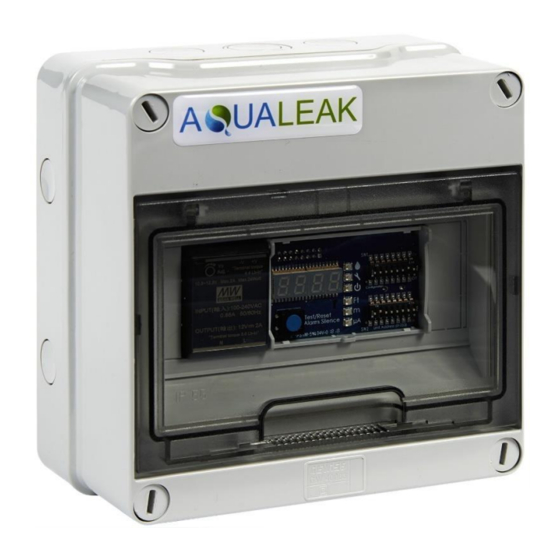
Page 7: Page Figure 1 Aqualeak 10K
10K uses sensing equipment (sold separately) to detect the presence of water and other liquids. If a leak is detected, an alarm is activated, the distance to the leak is displayed, and the Aqualeak 10K can report the presence of the leak to a Building Management System (BMS). -
Page 8: Description
10K manual DESCRIPTION Capable of accommodating up to 2500 m (8200 ft) of sensor cable, the Aqualeak 10K has an audible alarm and can communicate via Modbus. As a stand-alone solution, the Aqualeak 10K provides alarm notification, and numeric distances to leaks or problems, on its front panel. -
Page 9: Internal Description
Power Supply Unit (PSU). They are mounted on a standard DIN rail inside the back box of the 10K casing. To the left of the PSU are DIN rail mounted terminal blocks for the mains supply live, neutral and Earth connections. -
Page 10: Additional Items
1. A sensor cable. Aqualeak recommends that only the orange coloured sensor cable (Part No. SCTDM) designed to be used with the Aqualeak 10K is used. If the recommended sensor cable is used any length of sensor cable up to a maximum length of 2500 m (8200 ft) may be linked to the 10K. -
Page 11: Specification
10K manual SPECIFICATION The specification of the Aqualeak 10K is given in the following Table. Table 1 10K specification Aqualeak 10K Value Units Notes Dimensions 180 x 180 x 98 Width x height x depth Weight Supply Voltage 100 to 230... -
Page 12: Installation And Configuration
INSTALLATION AND CONFIGURATION PREPARATION FOR INSTALLATION Check that all items supplied with the Aqualeak 10K, and all optional items required for your installation, are present and undamaged. Refer to the list on Pages 10 and 11. If any items are missing or damaged, report it before installing the equipment. -
Page 13: Figure 4 Electrical Connections To Aqualeak 10K
5 Neutral bus bar 13 Earth terminal block 6 EIA-485 Comms Port 14 Neutral terminal block 7 10K Controller 15 Live terminal block 8 Relay Output (TB1) Figure 4 Electrical connections to Aqualeak 10K Issue 1.0, 31st July 2019 Page 13... -
Page 14: Tb1 Summary Relay (Optional)
A 4.57 m section of non-sensing leader cable is supplied with each Aqualeak 10K. The leader cable connects the sensing cable to the Aqualeak 10K, since sensing cable cannot connect directly to the 10K. Insert its four stripped wires into the appropriate slots in TB2 – from left to right: white, black, green, and red. -
Page 15: Tb3 And Tb4: Input Power And Eia-485 Communications Ports
Figure 9 SW1, DIP Switch 6 – Display cable length in feet or meters 2. Aqualeak’s orange sensing cable (Part No. SCTDM) has a resistance of 2.8 Ohms per foot. Set DIP switch 7 in block SW1 to the appropriate resistance-per-foot value;... -
Page 16: Figure 11 Tb3 And Tb4 Power Supply And Communications Connections
Aqualeak 10K’s circuitry will auto-correct. 4. If you are installing only one Aqualeak 10K and it will communicate via Modbus to a Modbus-enabled controller, use the three most right-hand pin-outs on TB3 or TB4 to connect the Aqualeak 10K to an EIA-485 network. -
Page 17: Jmp - Termination Jumper
Figure 14 SW1, DIP Switch 8 – Audible Alarm settings Set the Re-Alarm interval The Aqualeak 10K can be set to re-alarm. If set to re-alarm, when a leak or cable fault has been detected, the alarm will be re-sent at 4 hour intervals until the alarm condition has been resolved. -
Page 18: Connect The Leak Detection Cable
Figure 15 SW1, DIP Switch 4 – Re-Alarm interval CONNECT THE LEAK DETECTION CABLE The Aqualeak 10K is shipped with a 4.57 m leader cable. This leader cable was connected to the 10K as described on page 14. The following directions help you connect sensing cable to the Aqualeak 10K. -
Page 19: Secure Sensor Cable To The Floor
SHOULD NOT be installed in inaccessible areas and should always be retrievable for maintenance. Secure the sensor cable to the floor with either J-clips (Aqualeak Part No. #JC), or one of the other approved methods shown in Figure 18. Available from Aqualeak and designed specifically for use with sensing cable, J-clips are the manufacturer's recommended installation method. -
Page 20: Applying Power To The Aqualeak 10K
Apply power to the Aqualeak 10K as follows: WARNING – ELECTRIC SHOCK The Aqualeak 10K operates using mains voltage that is dangerous to life. Before applying power to the 10K, re-fit the front cover. Death, personal injury and/or damage to persons and/or property may result if this is not observed. -
Page 21: Test The System
10K manual 2. Make sure all connections are correct and all screw terminals are secure. 3. Fit the front panel to the Aqualeak 10K and secure with the four flat head screws retained when the front panel was removed. 4. Apply power to the Aqualeak 10K. The device will begin to boot. -
Page 22: Operation
OPERATION FRONT PANEL CONTROLS AND DISPLAY The front panel of the Aqualeak 10K contains a 4-character LED and series of coloured LEDs that are used together to convey device status and information regarding detected leaks and cable faults. A blue button is used to cycle the 4-character LED, silence the audible alarm, and reset the alarm. -
Page 23: Table 2 Front Panel Controls And Displays
10K manual Table 2 Front panel controls and displays Front Panel Indicator Symbol Description 4-character LED SH10 System is running in its normal operating state. 675 (e.g.) A leak, fault, or contamination has been detected. The numerical distance to the leak displays on the LED. A green... -
Page 24: Manage Alarms
10K manual MANAGE ALARMS General Guidelines 1. If the audible alarm sounds, briefly press the Test/Reset button to silence it. 2. Look at the display, or read the appropriate Modbus register, to determine the type of alarm and the distance to the leak, contamination, or cable break. -
Page 25: Modbus Communications
Communications Address on page 17 for more specific information. Function Field The function field is one byte in length and tells the Aqualeak 10K which function to perform. Functions 03 (Read 4xxxx output registers) and 04 (Read 3xxxx input registers) are supported by the Aqualeak 10K. -
Page 26: Packet Communications For The Aqualeak 10K
PACKET COMMUNICATIONS FOR THE AQUALEAK 10K Function 03: Read Output Registers To read the Aqualeak 10K parameter values, the master device must send a Read Output Registers request packet. The Read Output Registers request packet specifies a start register, and the number of registers to read. - Page 27 Units Range 40004 Latched Alarms Latched alarm requires 0 = Disabled 0-65535 (read-only) Aqualeak 10K to be reset 1 = Enabled once alarm is cleared. Note: Set with DIP SW1; Default: Disabled this register is read-only. 0 = Disabled 40005...
-
Page 28: Function 04: Read Input Registers
10K manual Function 04: Read Input Registers To read the Aqualeak 10K input values, the master must send a Read Input Registers request packet. The Read Input Registers request packet specifies a start register, and the number of registers to read. The start register is numbered from zero (30001 = zero, 30002 = one, etc). -
Page 29: Rtu Framing
1 = Leak detected 1 = Cable break detected 1 = Contamination detected 1 = Summary alarm 04-15 Spare RTU FRAMING The example below shows a typical Query/Response from an Aqualeak 10K. Table 9 Response sample Slave Function Count Register Register... -
Page 30: Calibrate Sensor Cable Length Via Modbus
10K manual CALIBRATE SENSOR CABLE LENGTH VIA MODBUS The length of sensor cable connected to the Aqualeak 10K can be calibrated through a Modbus-enabled system. This helps fine-tune a distance-read leak detection system. If no alarms are present, follow these steps to calibrate and test the system: 1. - Page 31 This milliOhms per foot value is your end result, and the number you will write to Modbus register 40008. Record this value. 10. Access your Modbus-enabled system. Write the milliOhms per foot resistance value to the Aqualeak 10K’s Modbus register 40008. Example •...
-
Page 32: Preventive Maintenance
PREVENTIVE MAINTENANCE Monthly Maintenance Follow these steps monthly to test the Aqualeak 10K and verify that the device is functioning properly. If your Aqualeak 10K is hooked into a BMS or NMS, notify monitoring personnel before you begin to test the system. -
Page 33: Troubleshooting
10K manual TROUBLESHOOTING In the event of a problem with the Aqualeak 10K, consult the Table below which contains troubleshooting procedures for the most likely problems. If the problem is different to those identified in Table 10, contact Aqualeak for assistance. -
Page 34: Repair
Contamination and/or physical damage to the sensor cable is not covered under warranty. Repair If the 10K requires repair and service, it must be either returned to Aqualeak, or an Aqualeak Installation Engineer called-out. When contacting Aqualeak for assistance, please have the following information available: 1. -
Page 35: Appendix A - Configuration Reference
DIP switches in blocks SW1 and SW2. The configuration of a stand-alone Aqualeak 10K can be performed using the DIP switches on the front panel. If the Aqualeak 10K is to be connected to a Modbus-equipped monitoring system, some of the configuration can be performed using the registers. -
Page 36: A2. Sw1 Dip Switch Settings
10K manual A2. SW1 DIP SWITCH SETTINGS DIP switch 1 manipulates basic configuration settings on the Aqualeak 10K. Dip switch 3 in SW1 is unused and should remain in the OFF position. Figure A2 SW1 DIP Switch configuration settings Issue 1.0, 31st July 2019... -
Page 37: A3. Sw2 Dip Switch Settings
SW1 to set the communication baud rate. Then, use the switches on DIP SW2 as follows for the communications you plan to employ. A3.1 Configure the Aqualeak 10K for Modbus Communications The Modbus address should be a number between 1 and 254. Adjust the individual switches until their sum equals the Modbus address.
Need help?
Do you have a question about the 10K and is the answer not in the manual?
Questions and answers