
Ansul R-102 Manuals
Manuals and User Guides for Ansul R-102. We have 5 Ansul R-102 manuals available for free PDF download: Installation And Maintenance Manual, Owner's Manual, User Manual
Advertisement

Ansul R-102 Installation And Maintenance Manual (189 pages)
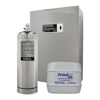
restaurant fire suppression system
Brand: Ansul
|
Category: Fire Alarms
|
Size: 7 MB
Table of Contents

Ansul R-102 Installation And Maintenance Manual (143 pages)
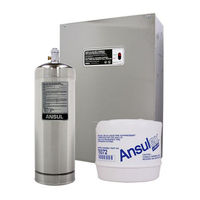
RESTAURANT FIRE SUPPRESSION SYSTEM
Brand: Ansul
|
Category: Commercial Food Equipment
|
Size: 1 MB
Table of Contents
Advertisement
Ansul R-102 Owner's Manual (4 pages)
RESTAURANT FIRE SUPPRESSION SYSTEM
Brand: Ansul
|
Category: Commercial Food Equipment
|
Size: 0 MB
Table of Contents

Ansul R-102 Owner's Manual (4 pages)
RESTAURANT FIRE SUPPRESSION SYSTEM
Brand: Ansul
|
Category: Safety Equipment
|
Size: 0 MB
Advertisement