Sign In
Upload
Manuals
Brands
Anschutz Manuals
Amplifier
139-158.SA001 E01
Anschutz 139-158.SA001 E01 Manuals
Manuals and User Guides for Anschutz 139-158.SA001 E01. We have
1
Anschutz 139-158.SA001 E01 manual available for free PDF download: Operator's And Service Manual
Anschutz 139-158.SA001 E01 Operator's And Service Manual (69 pages)
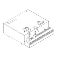
FU Amplifier AS
Brand:
Anschutz
| Category:
Amplifier
| Size: 11 MB
Table of Contents
Table of Contents
3
List of Figures
7
List of Tables
9
List of Abbreviations
11
Introduction
13
Preliminary Remarks
13
Change History
13
Safety
13
General Safety Regulations
13
Tab. 1: Change History
13
General Safety Instructions
14
Electrostatic Discharge
14
Fig. 1: Electrostatic Discharge, Protected Area
14
List of Further Documents
15
List of Annex Documents
15
Tab. 2: List of Further Documents
15
Tab. 3: Dimensional Drawings
15
Tab. 4: Wiring Diagrams
15
1 Description
16
Purpose
16
Technical Data
16
Interfaces
16
Technical Description
17
CAN Bus Technology
17
Fig. 2: CAN Bus, Jumper for Termination
18
Tab. 5: CAN Bus, Cable Requirements
18
Operating Elements and Indicators
19
Fig. 3: PCB, Operating Elements and Indicators
19
Functional Description
21
Dead Band
21
Rudder Lead
22
Rudder Stop
22
Analog Output Modes
22
Modes of Operation
22
Normal Operation
23
Operation Mode Follow-Up (FU)
23
Operation Mode Non-Follow-Up (NFU)
23
Dependence on Peripheral Systems / Devices
23
Outfit and Accessories
24
Fig. 4: FU Amplifier AS, Application
24
2 Operation
25
Preliminary Remarks
25
Safety Instructions for Operation
25
Setting into Operation
26
Pre-Operation Procedures after Longer Time Setting out of Operation
26
Setting out of Operation
26
Procedures for Longer Time Setting out of Operation
26
3 Troubleshooting
27
Troubleshooting Table
27
4 Installation and Maintenance
29
Safety Instructions for Installation and Maintenance
29
General Information
29
Reference to ISPC
29
Special Tools, Measurement and Test Equipment
30
List of Consumables
30
Installation
30
Cable Connections
30
Safety Instructions for Cable Connections
30
General Remarks about Preparing Cable Connections
31
Fig. 5: Prepare a Cable Connection
31
Fig. 6: Prepare a Cable Entry
32
Fig. 7: Example for Cable Connections
32
General Remarks about Preparing Common Ground Connections
33
Supply Voltage Selection
33
Fig. 8: Prepare a Common Ground Connection
33
Supply Voltage 230 V or 380 V to 460 V at Plug B1, B2 (NG001)
34
Fig. 9: Type NG001, Supply Voltage Connection at Plug B1, B2
34
Fig. 10: Type NG001, Principle of Supply Voltage Selection
35
Tab. 6: Type NG001, Supply Voltage Selection
35
Supply Voltage 115 V or 230 V at Plug B1, B2 (NG002)
36
Fig. 11: Type NG002, Supply Voltage Connection at Plug B1, B2
36
Fig. 12: Type NG002, Principle of Supply Voltage Selection
37
Tab. 7: Type NG002, Supply Voltage Selection
37
CAN Bus to Actuator Connection at Plugs B7, B8
38
Fig. 13: CAN Bus to Actuator Connection at Plugs B7, B8
38
CAN Bus Application in a Steering Control System
39
CAN Bus to Service Tool Connection at Plug B7, B8
39
Fig. 14: Example of CAN Bus Application in Steering Control System
39
Tab. 8: Plug B7, B8, Allocation of Terminal 2, 3, 4
39
Connection to Rudder Feedback Unit as (Single CAN Bus) at Plug B9
40
Fig. 15: CAN Bus and Supply Voltage Connection to Rudder Feedback Unit as at Plug B9
40
Connection of Analog Outputs (Set Rudder) at Plugs B5, B6
41
Fig. 16: Connection of Analog Outputs at Plugs B5, B6
41
Connection Control Signal to Pump Valves at Plugs B14, B15
42
Connection of Status Signals at Plugs B12, B13
42
Fig. 17: Connection Control Signal to Pump Valves at Plugs B14, B15
42
Fig. 18: Connection of Status Signals at Plugs B12, B13
43
Tab. 9: Inputs at Plug B13
43
Tab. 10: Outputs at Plug B12
43
Connection of External 24 V DC Voltage Supply at Plug B4
44
Configuration
45
Fig. 19: Connection of External Voltage Supply at Plug B4
45
Tab. 11: Inputs at Plug B4
45
Tab. 12: Menu Structure for Configuration
46
Activate Display on PCB and Navigate through the Menus
47
Rudder Scale
47
Tab. 13: Pushbuttons and Indicators for Configuration
47
Set Rudder Scale
48
Dead Band
48
Set Dead Band
48
Rudder Pulse
49
Set Rudder Pulse
49
Rudder Lead
49
Set Rudder Lead
50
Analog Gain
50
Set ANALOG GAIN
50
Steering Fail
51
Set Steering Fail Threshold / Delay
51
Show Alarm List (Error Log Entries)
51
Tab. 14: Error Log, Possible Entries
52
Show / Delete Error Log Entries
53
Show Active Faults
53
Show Settings
53
Tab. 15: Displayed Settings
54
Show Settings
57
Bite / Fram
57
Store Settings to FRAM
57
Start BITE
58
Rudder Com
58
Set Rudder Com
58
Care and Maintenance
58
Repair
59
Reference to ISPC
59
5 Transport and Storage
60
Preservation, Packing and Storage
60
Transport
61
6 Disposal
62
7 Illustrated Spare Parts Catalog
63
General Remarks
63
Definitions
63
8 Annex
64
Recommended Setting to Work Procedure
64
Drawings
65
Advertisement
Advertisement
Related Products
Anschutz 139-158.NG001 E01
Anschutz 139-158.NG002 E01
Anschutz 139-159.NG001
Anschutz 139-159.NG002
Anschutz 139-159.NG003
Anschutz 133-811.NG001
Anschutz 136-065
Anschutz 138-133.NG001 E01
Anschutz 135-111.NG003
Anschutz 138-128.NG001
Anschutz Categories
Security System
Marine Equipment
Industrial Equipment
Compass
Control Unit
More Anschutz Manuals
Login
Sign In
OR
Sign in with Facebook
Sign in with Google
Upload manual
Upload from disk
Upload from URL