
Summary of Contents for Anschutz 139-158.NG001 E01
- Page 1 Anschütz GmbH Zeyestr. 16-24 24106 Kiel Germany www.anschuetz.com FU Amplifier AS Operator and Service Manual Type: 139-158.NG001 E01 Type: 139-158.NG002 E01 Type: 139-158.SA001 E01 Edition: 001 10000001982...
- Page 2 Copyright Dieses Dokument sowie dessen Inhalt sind urheberrechtlich This document and its content are copyright protected. Distribution, geschützt. Die Weitergabe,Vervielfältigung und Speicherung sowie reproduction and storage as well as translation and exploitation of die Übersetzung wie auch Verwendung dieses Dokuments oder this document and its content, in whole or in parts and regardless of dessen Inhalts, als Ganzes oder in Teilen und egal in welcher Form what form, are prohibited without prior express written permission.
-
Page 3: Table Of Contents
FU Amplifier AS Table of Contents Table of Contents List of Figures..............................V List of Tables..............................VII List of Abbreviations............................IX Introduction................................ 1 Preliminary Remarks............................. 1 Change History.............................. 1 Safety................................1 General Safety Regulations........................1 General Safety Instructions........................2 Electrostatic Discharge..........................2 List of Further Documents..........................3 List of Annex Documents.......................... - Page 4 FU Amplifier AS Table of Contents 4.1 Safety Instructions for Installation and Maintenance................17 4.2 General Information..........................17 4.2.1 Reference to ISPC.........................17 4.2.2 Special Tools, Measurement and Test Equipment............... 18 4.2.3 List of Consumables........................18 4.3 Installation............................... 18 4.3.1 Cable Connections.........................18 4.3.1.1 Safety Instructions for Cable Connections................18 4.3.1.2 General Remarks about Preparing Cable Connections............
- Page 5 FU Amplifier AS Table of Contents 5 Transport and Storage..........................48 5.1 Preservation, Packing and Storage....................... 48 5.2 Transport..............................49 6 Disposal................................50 7 Illustrated Spare Parts Catalog........................51 7.1 General Remarks........................... 51 7.2 Definitions............................... 51 7.3 FU Amplifier AS............................51 8 Annex................................52 8.1 Recommended Setting to Work Procedure................... 52 8.2 Drawings..............................53 Edition: 001 10000001982...
- Page 6 FU Amplifier AS Table of Contents 10000001982 Edition: 001...
-
Page 7: List Of Figures
FU Amplifier AS List of Figures List of Figures Fig. 1: Electrostatic Discharge, Protected Area..................... 2 Fig. 2: CAN Bus, Jumper for Termination......................6 Fig. 3: PCB, Operating Elements and Indicators....................7 Fig. 4: FU Amplifier AS, Application........................12 Fig. 5: Prepare a Cable Connection........................19 Fig. - Page 8 FU Amplifier AS List of Figures 10000001982 Edition: 001...
-
Page 9: List Of Tables
FU Amplifier AS List of Tables List of Tables Tab. 1: Change History............................1 Tab. 2: List of Further Documents......................... 3 Tab. 3: Dimensional Drawings..........................3 Tab. 4: Wiring Diagrams............................3 Tab. 5: CAN Bus, Cable Requirements......................... 6 Tab. 6: Type NG001, Supply Voltage Selection....................23 Tab. - Page 10 FU Amplifier AS List of Tables 10000001982 VIII Edition: 001...
-
Page 11: List Of Abbreviations
FU Amplifier AS List of Abbreviations List of Abbreviations BITE Built-In Test Equipment Controller Area Network Central Processing Unit ESD Protected Area Electrostatic Discharge FRAM Ferroelectric Random Access Memory Follow-Up Ground ISPC Illustrated Spare Parts Catalog Non-Follow-Up Universal Time, Coordinated stbd Starboard Edition: 001... - Page 12 FU Amplifier AS List of Abbreviations 10000001982 Edition: 001...
-
Page 13: Introduction
FU Amplifier AS Introduction Introduction Preliminary Remarks The present manual is a description and reference book only. It is intended to answer questions and to solve problems in the quickest possible manner. Read and follow the instructions and notes in this manual before operating the equipment. For this purpose, refer to the table of contents and read the corresponding chapters thoroughly. -
Page 14: General Safety Instructions
FU Amplifier AS Introduction WARNING! Warning statements indicate a hazardous situation that, if not avoided, could result in minor, moderate or serious injury, or death Consequence • Preventive action CAUTION! Caution statements indicate a hazardous situation that, if not avoided, could result in material damage Consequence •... -
Page 15: List Of Further Documents
FU Amplifier AS Introduction Dissipative Shoes Floor Mat Wrist Band Wrist Strap Common Ground Ground Point Any product which is labeled as shown is electrostatic sensitive. If proper Electrostatic Discharge (ESD) precautions are not taken, handling or working on this product results in damage. Every action must be done under ESD protection. The product and all electronic parts of the product are susceptible to ESD. -
Page 16: Description
FU Amplifier AS 1 Description 1 Description 1.1 Purpose The FU Amplifier AS is a central component of the rudder control system. It controls the hydraulic valves of the steering gear until the rudder's actual value has reached the set value of the rudder. 1.2 ... -
Page 17: Technical Description
FU Amplifier AS 1 Description Designation Data / Signal Plug Output / Input CAN bus According to Anschütz dual CAN bus specification B7, B8, B9 Input load (status contacts): 24 V, Imax. 5 mA Output load (status/alarm contacts): 30 V, Imax. 1 A 1.3 ... -
Page 18: Fig. 2: Can Bus, Jumper For Termination
FU Amplifier AS 1 Description Fig. 2: CAN Bus, Jumper for Termination CAN bus termination (T) CAN bus low (L) The minimum cable requirements for the CAN bus are: Tab. 5: CAN Bus, Cable Requirements Term Designation 2 x 2 x 0.75 mm , screened, twisted pair (twisted pitch length Type <... -
Page 19: Operating Elements And Indicators
FU Amplifier AS 1 Description 1.4 Operating Elements and Indicators Fig. 3: PCB, Operating Elements and Indicators Element Description Plug B5 Analog set rudder output (analog2) LED H5 Processor clock, flashes green in normal operation flashes red in case of a system fail flashes blue for development only Plug B6 Analog set rudder output (analog1) LED H2... - Page 20 FU Amplifier AS 1 Description Element Description LED H6 Analog Output1 (set rudder) supply voltage +15 V DC, lights up green if present LED H7 Analog Output2 (set rudder) supply voltage +15 V DC, lights up green if present Pushbutton B35 RESET microprocessor DIP switches Development only...
-
Page 21: Functional Description
FU Amplifier AS 1 Description Element Description Plug B4 24 V DC supply for external devices (as Steering Interface, Handwheel) Plug B8 CAN bus2, Input/output via Steering Interface AS Plug B7 CAN bus1, Input/output via Steering Interface AS Plug B1 Input AC1, Supply voltage from pump1 via starter box LED H14 CAN bus2 of dual CAN-bus, lights up green if supply voltage of 5 V DC is present... -
Page 22: Rudder Lead
FU Amplifier AS 1 Description pump 1 or pump 2 or pump 1 and pump 2. 1.5.2 Rudder Lead At rudder machines with a big delay, the rudder lead parameter can be switched on. The adaption depends on the status of pump 1 and pump 2 and the tune is aligned to the delay. -
Page 23: Normal Operation
FU Amplifier AS 1 Description • (FU), see chapter 1.5.6.1 Follow-Up • Non-Follow-Up (NFU), see chapter 1.5.6.2 1.5.6 Normal Operation 1.5.6.1 Operation Mode Follow-Up (FU) In operation mode FU, the comparison (set rudder - actual rudder) is recognized as controller difference and activates the switching outputs. Depending on the sign of this difference the port or starboard valve of the pump is opened. -
Page 24: Outfit And Accessories
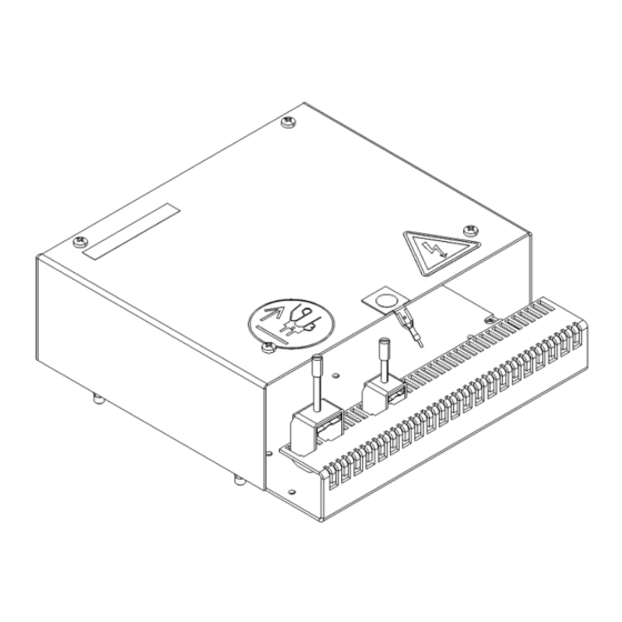
FU Amplifier AS 1 Description Fig. 4: FU Amplifier AS, Application 1.7 Outfit and Accessories This system or equipment comprises no outfit or accessories. 10000001982 Edition: 001... -
Page 25: Operation
FU Amplifier AS 2 Operation 2 Operation 2.1 Preliminary Remarks User Rights The manual is a complete documentation of the system or equipment. Some functions may not be accessible depending on user rights. All functions or operations are described irrespective of the actual user rights of the user. Markup Elements The manual uses different markup elements for hardware and software. -
Page 26: Setting Into Operation
FU Amplifier AS 2 Operation 2.3 Setting into Operation 2.3.1 Pre-Operation Procedures after Longer Time Setting out of Operation This system or equipment requires no special pre-operation procedures after longer time setting out of operation. 2.3.2 Setting into Operation Procedure 1. Connect the supply voltage. ►... -
Page 27: Troubleshooting
FU Amplifier AS 3 Troubleshooting 3 Troubleshooting It is recommended to restart the FU Amplifier AS before replacing the complete device. 3.1 Troubleshooting Table Note Observe all safety regulations and general remarks about installation, see chapter 4.1. Failure Possible Cause Remedy DAC1 FAIL Error after BITE Remove analog output... - Page 28 FU Amplifier AS 3 Troubleshooting Failure Possible Cause Remedy SYS FAIL Steering Inter- 24 V DC supply Overload (PTC active) face • Rudder Feedback Unit Disconnect both units and WIRE BREAK, SYS FAIL AS is OFF check for possible reason. • Steering Interface AS is OFF FU FB FAILED...
-
Page 29: Installation And Maintenance
FU Amplifier AS 4 Installation and Maintenance 4 Installation and Maintenance 4.1 Safety Instructions for Installation and Maintenance WARNING! Danger due to maintenance and service by unskilled personnel Risk of serious injury and material damage • Keep all unskilled personnel away from the working area. •... -
Page 30: Special Tools, Measurement And Test Equipment
FU Amplifier AS 4 Installation and Maintenance Note All spare parts that are produced by Anschütz GmbH are identified in the ISPC by a seven-digit part number. This part number is included in the serial number on the type plate of the equipment. The first 7 digits of the serial number are formed by the part number. -
Page 31: General Remarks About Preparing Cable Connections
FU Amplifier AS 4 Installation and Maintenance WARNING! Danger due to damaged cable coating Risk of fire or electrical shock • Do not bend cables to an acute angle, pinch, twist, or impact excessive force while connecting cables to the equipment. •... -
Page 32: Fig. 6: Prepare A Cable Entry
FU Amplifier AS 4 Installation and Maintenance Fig. 6: Prepare a Cable Entry 7. Insert the earthing insert, the seal, and the washer into the cable gland, place the counter nut last and tighten the nut hand-tight. 8. Strip the cable cores to a length of approx. 15 mm, twist slightly and clamp on the cable end sleeves. -
Page 33: General Remarks About Preparing Common Ground Connections
FU Amplifier AS 4 Installation and Maintenance 4.3.1.3 General Remarks about Preparing Common Ground Connections In order to comply with the stringent requirements, please follow the instructions given below regarding cable connections. Use the cable types specified. CAUTION! Damage to Equipment and Components It is essential to make sure that any equipment and any additional component (options) have common reference to the ship's common ground. -
Page 34: Supply Voltage 230 V Or 380 V To 460 V At Plug B1, B2 (Ng001)
FU Amplifier AS 4 Installation and Maintenance 4.3.1.5 Supply Voltage 230 V or 380 V to 460 V at Plug B1, B2 (NG001) WARNING! Danger due to electrical current Risk of death or serious injury that is caused by electrical shock •... -
Page 35: Fig. 10: Type Ng001, Principle Of Supply Voltage Selection
FU Amplifier AS 4 Installation and Maintenance Tab. 6: Type NG001, Supply Voltage Selection Plug / Terminal Supply Voltage Jumper Plug B1 Plug B2 B1/1, B2/1 Jumper between ter- Jumper between ter- minals minals 230 V AC 1 and 2 1 and 2 B1/4, B2/4 3 and 4 3 and 4... -
Page 36: Supply Voltage 115 V Or 230 V At Plug B1, B2 (Ng002)
FU Amplifier AS 4 Installation and Maintenance 4.3.1.6 Supply Voltage 115 V or 230 V at Plug B1, B2 (NG002) WARNING! Danger due to electrical current Risk of death or serious injury that is caused by electrical shock • Disconnect voltage supply before starting work. •... -
Page 37: Fig. 12: Type Ng002, Principle Of Supply Voltage Selection
FU Amplifier AS 4 Installation and Maintenance Tab. 7: Type NG002, Supply Voltage Selection Plug / Terminal Supply Voltage Jumper Plug B1 Plug B2 B1/1, B2/1 Jumper between ter- Jumper between ter- minals minals 115 V AC 1 and 2 1 and 2 B1/4, B2/4 3 and 4 3 and 4... -
Page 38: Can Bus To Actuator Connection At Plugs B7, B8
FU Amplifier AS 4 Installation and Maintenance 4.3.1.7 CAN Bus to Actuator Connection at Plugs B7, B8 Fig. 13: CAN Bus to Actuator Connection at Plugs B7, B8 Plug / Terminal Remarks B7/1, B8/1 CAN termination (jumper between terminal 1 and 2) B7/2, B8/2 CAN low B7/3, B8/3... -
Page 39: Can Bus Application In A Steering Control System
FU Amplifier AS 4 Installation and Maintenance 4.3.1.8 CAN Bus Application in a Steering Control System There are 2 CAN bus systems in a steering control system application possible: a dual CAN bus and a single CAN bus. The dual CAN bus is a redundant bus system (CAN1 and CAN2). The single CAN bus (CAN0) is used between FU Amplifier AS and Rudder Feedback Unit AS. -
Page 40: Connection To Rudder Feedback Unit As (Single Can Bus) At Plug B9
FU Amplifier AS 4 Installation and Maintenance 4.3.1.10 Connection to Rudder Feedback Unit AS (Single CAN Bus) at Plug B9 Fig. 15: CAN Bus and Supply Voltage Connection to Rudder Feedback Unit AS at Plug B9 Plug / Terminal Remarks B9/1 +24 V DC supply B9/2 Reference to +24 V DC supply... -
Page 41: Connection Of Analog Outputs (Set Rudder) At Plugs B5, B6
FU Amplifier AS 4 Installation and Maintenance 4.3.1.11 Connection of Analog Outputs (Set Rudder) at Plugs B5, B6 Fig. 16: Connection of Analog Outputs at Plugs B5, B6 Plug / Terminal Galvanically isolated set rudder output voltage B5/1, B6/1 ±10 V DC set voltage (+) B5/2, B6/2 Reference to ±10 V DC set voltage (-) Edition: 001... -
Page 42: Connection Control Signal To Pump Valves At Plugs B14, B15
FU Amplifier AS 4 Installation and Maintenance 4.3.1.12 Connection Control Signal to Pump Valves at Plugs B14, B15 Fig. 17: Connection Control Signal to Pump Valves at Plugs B14, B15 Plug / Terminal Remarks B14/2, B15/2 Common + ON/OFF Port valve B14/4, B15/4 Common + ON/OFF Stbd valve... -
Page 43: Fig. 18: Connection Of Status Signals At Plugs B12, B13
FU Amplifier AS 4 Installation and Maintenance Fig. 18: Connection of Status Signals at Plugs B12, B13 Tab. 9: Inputs at Plug B13 Plug / Terminal Remarks B13/1 Status1 (main/secondary) * B13/2 Reference to status1 * B13/3 Status2 (stop) * B13/4 Reference to status2 * * has to be configured Status information could be:... -
Page 44: Connection Of External 24 V Dc Voltage Supply At Plug B4
FU Amplifier AS 4 Installation and Maintenance Plug / Terminal Remarks B12/7 WIRE BREAK B12/8 Alarm contacts version E01 (normally closed contacts): B12/5 STEERING FAIL B12/6 B12/7 WIRE BREAK B12/8 4.3.1.14 Connection of External 24 V DC Voltage Supply at Plug B4 Note Only for version SA001. -
Page 45: Configuration
FU Amplifier AS 4 Installation and Maintenance Fig. 19: Connection of External Voltage Supply at Plug B4 Tab. 11: Inputs at Plug B4 Plug / Terminal Remarks B4/1 +24 V DC B4/2 Note Plug B4 is designed to lead supply voltage also to other loads. 4.4 ... -
Page 46: Tab. 12: Menu Structure For Configuration
FU Amplifier AS 4 Installation and Maintenance Note Only Anschütz service personnel is permitted to use the Service Tool. Configurable parameters are set by scrolling through a menu structure (PCB must include display and pushbuttons). The initial main menu is Rudder Adjustment. Tab. -
Page 47: Activate Display On Pcb And Navigate Through The Menus
FU Amplifier AS 4 Installation and Maintenance 4.4.1 Activate Display on PCB and Navigate through the Menus Procedure 1. Press pushbutton F+, F-, SET, + or -. ► The display is active. ► The initial main menu RUDDER ADJUSTMENT is opened. 2. -
Page 48: Set Rudder Scale
FU Amplifier AS 4 Installation and Maintenance 4.4.2.1 Set Rudder Scale Procedure 1. Activate the display, see chapter 4.4.1. 2. Select main menu RUDDER ADJUSTMENT. ► A menu opens. 3. Select RUDDER SCALE. ► A dialog opens. 4. Set a value. 5. -
Page 49: Rudder Pulse
FU Amplifier AS 4 Installation and Maintenance ► The value is set. 7. Select BACK to leave the dialog. 4.4.4 Rudder Pulse This parameter is for tests by Anschütz service personnel only. It can be switched ON/OFF via the Service Tool. Parameter Entry / Options Default... -
Page 50: Set Rudder Lead
FU Amplifier AS 4 Installation and Maintenance 4.4.5.1 Set Rudder Lead Procedure 1. Activate the display, see chapter 4.4.1. 2. Select main menu RUDDER ADJUSTMENT. ► A menu opens. 3. Select RUDDER LEAD. ► The menu RUDDER LEAD opens. 4. Make a choice out of the following options: a) To set RUDDER LEAD P1, select RUDDER LEAD P1. -
Page 51: Steering Fail
FU Amplifier AS 4 Installation and Maintenance 6. Press pushbutton SET to confirm. ► The value is set. 7. Select BACK to leave the dialog. 4.4.7 Steering Fail These parameters are used to configure steering fail monitoring. Parameter Entry / Options Default Description Sets threshold in de- grees for the difference... -
Page 52: Tab. 14: Error Log, Possible Entries
FU Amplifier AS 4 Installation and Maintenance The error log shows all failure messages in sequence and additional time information of occurrence. Tab. 14: Error Log, Possible Entries Log Entry Description POWER FAIL CAN 0 Internal CAN0 voltage supply missing POWER FAIL CAN 1 Internal CAN1 voltage supply missing POWER FAIL CAN 2 Internal CAN2 voltage supply missing... -
Page 53: Show Active Faults
FU Amplifier AS 4 Installation and Maintenance 4.4.8.1 Show Active Faults Procedure 1. Activate the display, see chapter 4.4.1. 2. Select main menu SHOW ALARM LIST. ► A menu opens. 3. Select ACTIVE FAULT. ► A dialog opens. 4. Make a choice out of the following options: a) To show active faults, select ACTIVE FAULT. -
Page 54: Tab. 15: Displayed Settings
FU Amplifier AS 4 Installation and Maintenance Note Not all settings can be performed at the FU Amplifier AS Some of these settings must be performed with the Service Tool (as there are system settings) or must be performed with local configuration of other devices in the steering control system Tab. - Page 55 FU Amplifier AS 4 Installation and Maintenance Menu Setting Description RU.STOP Shows status of signal output 0 = disabled 1 = enabled PULS Shows status of dead band pulse (for development only) 0 = disabled 1 = enabled RU. LIMIT Shows status of evaluation of rudder limit function, ON - OFF 0 = disabled 1 = enabled...
- Page 56 FU Amplifier AS 4 Installation and Maintenance Menu Setting Description STEE. CH1+2 Shows status of steering output1+2 connection to valve 0 = No 1 = Yes AC1 33.0V Shows supply voltage from pump1 (transformed to 33 V AC) AC2 33.0V Shows supply voltage from pump2 (transformed to 33 V AC) OLED 3.3V Shows display supply voltage...
-
Page 57: Show Settings
FU Amplifier AS 4 Installation and Maintenance Menu Setting Description SERIAL NO. Shows serial number TYPE NO. Shows type info REMARKS Shows remarks DESCRIPTION Shows description 4.4.9.1 Show Settings Procedure 1. Activate the display, see chapter 4.4.1. 2. Select main menu SHOW SETTINGS. ►... -
Page 58: Start Bite
FU Amplifier AS 4 Installation and Maintenance 4.4.10.2 Start BITE Procedure 1. Activate the display, see chapter 4.4.1. 2. Select main menu BITE/FRAM. ► A menu opens. 3. Select BITE SYSTEM. ► A dialog opens. 4. Select BITE START. 5. Press pushbutton SET to confirm. ►... -
Page 59: Repair
FU Amplifier AS 4 Installation and Maintenance 4.6 Repair A repair of the FU Amplifier AS is performed as a replacement of the complete device. After replacement, the FU Amplifier AS must be checked for correct functioning. 4.6.1 Reference to ISPC All maintenance tasks comprise information about the support equipment, consumables and spare parts that are used in this task. -
Page 60: Transport And Storage
FU Amplifier AS 5 Transport and Storage 5 Transport and Storage 5.1 Preservation, Packing and Storage Preservation All components / devices require no special preservation procedures. Packing All components / devices are packed with a special protection against humidity. The package contains desiccants and a humidity indicator. The humidity indicator can be read from the outside through a window and must be checked regularly. -
Page 61: Transport
FU Amplifier AS 5 Transport and Storage Color Indication Inside Humidity Necessary Action 40 % patch: pink > 40 % Desiccants must be replaced Components / devices must be checked for hu- midity, 50 % patch: pink > 50 % Desiccants must be replaced, Packaging must be checked for damages Note Opening and closing the packing to exchange the desiccants must be done by... -
Page 62: Disposal
FU Amplifier AS 6 Disposal 6 Disposal The FU Amplifier AS or components of it can be disposed according to the respective national regulations for electronic waste without harmful materials (according to Directive 2012/19/EU on waste electrical and electronic equipment (WEEE)). 10000001982 Edition: 001... -
Page 63: Illustrated Spare Parts Catalog
FU Amplifier AS 7 Illustrated Spare Parts Catalog 7 Illustrated Spare Parts Catalog 7.1 General Remarks All depicted items in the following figure(s) which are not mentioned in the corresponding table(s) are not available as spare part for this unit. Since further development may cause modifications to existing equipment, its conformity with the relevant illustrations and drawings is not always ensured. -
Page 64: Annex
FU Amplifier AS 8 Annex 8 Annex 8.1 Recommended Setting to Work Procedure Requirements Feedback is adjusted, see Tab. 2 Rudder Feedback Unit AS Operator and Service Manual Procedure 1. Ascertain the supply voltage and set the jumpers accordingly, see chapter 4.3.1.4. -
Page 65: Drawings
FU Amplifier AS 8 Annex c) Continue with pump2 with the same procedure. d) Continue with pump1 and 2 with the same procedure. 9. Optimize parameter setting in analog mode, see chapter 4.4.6. a) Select Trans mode and check if the rudder is working within the desired range. ►... - Page 66 FU Amplifier AS 8 Annex 10000001982 Edition: 001...
Need help?
Do you have a question about the 139-158.NG001 E01 and is the answer not in the manual?
Questions and answers