Sign In
Upload
Manuals
Brands
Anschutz Manuals
Control Unit
130-626.NG002
Anschutz 130-626.NG002 Manuals
Manuals and User Guides for Anschutz 130-626.NG002. We have
1
Anschutz 130-626.NG002 manual available for free PDF download: Operator's And Service Manual
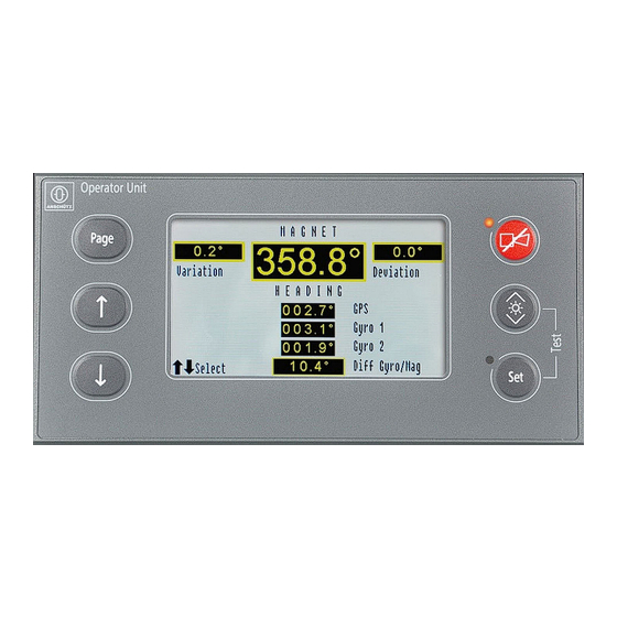
Anschutz 130-626.NG002 Operator's And Service Manual (102 pages)
Operator Unit Gyro Compass
Brand:
Anschutz
| Category:
Control Unit
| Size: 13 MB
Table of Contents
Table of Contents
3
List of Figures
7
List of Abbreviations
11
Introduction
13
Preliminary Remarks
13
Change History
13
Safety
13
General Safety Regulations
13
Tab. 1: Change History
13
Safety Regulations
14
Electrostatic Discharge
15
Fig. 1: Electrostatic Discharge, Protected Area
15
Standard Compliancy
16
List of Further Documents
16
Tab. 2: List of Standards
16
Tab. 3: List of Further Documents
16
List of Annex Documents
17
Tab. 4: Dimensional Drawings
17
Tab. 5: Wiring Drawings
17
Tab. 6: Configuration Sheets
17
Description
18
Purpose
18
Technical Data
18
Technical Description
18
Serial Interface
19
Fig. 2: Operator Unit, Flush Mounted
19
Configurable Parameters
21
Operating Elements and Indicators
21
Fig. 3: Operating Elements and Indicators, Gyro Compass Selected
21
Fig. 4: Operating Elements and Indicators, Magnetic Compass Selected
23
Operating Elements and Indicators on CPU PCB
24
Fig. 5: CPU PCB, Operating Elements and Indicators
24
Operating Elements and Indicators on Connection PCB
25
Fig. 6: Connection PCB, Operating Elements and Indicators
25
Functional Description
28
Dimming
28
Quick Settling
28
CAN Bus
29
Fig. 7: CAN Bus, Block Diagram
29
Gyro Compass System Remote Control
30
General Error Messages
30
Main Pages
30
Fig. 8: Display Page: no CAN Connection
30
Main Page: Overview
31
Display Page: Gyro Compass Selected
31
Display Page: Magnetic Compass Selected
31
Main Page: Heading Monitoring / Service
32
Fig. 9: Display Page: Heading Monitoring
32
Display Page: Auto Heading
33
Fig. 10: Display Page: Enter Service Mode
33
Fig. 11: Display Page: Auto Heading
34
Display Page: Speed Error Correction
35
Fig. 12: Display Page: Speed Error Correction
35
Display Page: DV-Bus
36
Display Page: Speed Source du
37
Fig. 13: Display Page: DV-Bus
37
Fig. 14: Display Page: Speed Source du
37
Display Page: Heading Uncorrected
38
Display Page: Rate of Turn
38
Fig. 15: Display Page: Heading Uncorrected
38
Display Page: Deviation Table
39
Fig. 16: Display Page: Rate of Turn
39
Display Page: Gyro Data
40
Fig. 17: Display Page: Deviation Table
40
Fig. 18: Display Page: Gyro Data
41
Display Page: CAN-Devices
42
Fig. 19: Display Page: CAN-Devices
42
Display Page: Software Versions
43
Main Page: Heading and Rot
43
Fig. 20: Display Page: Software Versions (Figure May Vary from Actual Device)
43
Main Page: Rot / Roll / Pitch
44
Fig. 21: Main Page: Heading
44
Main Page: Alerts
45
Fig. 22: Main Page: Rot / Roll / Pitch
45
Bridge Alert Management
46
Fig. 23: Main Page: Alerts, Unacknowledged
46
Tab. 7: Alert List, Alarm Symbols
47
Tab. 8: Alert List, Warning Symbols
48
Tab. 9: Alert List, Caution Symbols
48
Tab. 10: Alert Signaling
48
Tab. 11: Acknowledge Not Allowed Symbols
49
Operation
50
Preliminary Remarks
50
Safety Instructions for Operation
50
Setting into Operation
51
Pre-Operation Procedures after Longer Time Setting out of Operation
51
Heading Indication from Gyro System after Switching on
51
Fig. 24: Display Page: Heating Stage
52
Fig. 25: Display Page: Settling Stage
52
Activate Quick Settling
53
Fig. 26: Display Page: Quick Settling Possible
53
Fig. 27: Display Page: Quick Settling Activated
53
Normal Operation Procedures
54
General Settings
54
Select a Menu
54
Change Values
54
Confirm Settings
54
Adjust Brightness
55
Color Modes
55
Fig. 28: Display Page: Color Mode
55
Select Display Synchronization and Color Mode for Day and Night
56
Switch between Preset Day / Night Mode
56
Perform Lamp Test
57
Page Settings
57
Change Current Sensor
57
Fig. 29: Perform Lamp Test
57
Change Speed
58
Change Latitude
58
Change Variation
59
Set Heading Monitoring
59
Set Threshold for Heading Monitoring
60
Fig. 30: Display Page: Heading Difference
60
Service Page Settings
61
Open Service Mode
61
Fig. 31: Display Page: Service Mode
61
Set Switchover Auto Heading
62
Fig. 32: Display Page: Service Mode, Submenus
62
Fig. 33: Display Page: Auto Heading, Set Switchover
62
DV Bus Settings
63
Fig. 34: Display Page: Submenu DV Bus
63
Connect DV Bus
64
Assign DV Bus Address
64
Change Speed Source du
65
Fig. 35: Display Page: Speed Source du
65
Edit Deviation Table
66
Edit Deviation Table in a GG-R System
66
Select Damping of Rate of Turn
67
Set Speed Error Correction
67
Emergency Operation Procedures
68
Setting out of Operation
68
Procedures for Longer Time Setting out of Operation
68
Fig. 36: Display Page: Speed Error Correction, Restart Distribution Unit and Operator Unit
68
Troubleshooting
69
Safety Information on Troubleshooting
69
Alert / Status Message Handling
69
General Information on Alert Messages
69
Supported Alerts and Their Properties
70
Tab. 12: Operator Unit, Alert List
70
Responsibility Transfer
72
Temporary Silencing
73
Interfaces
73
Troubleshooting Table
73
Tab. 13: Troubleshooting Table
73
Installation
77
Cable Connections
77
Safety Instructions for Cable Connections
77
General Remarks about Preparing Cable Connections
78
Fig. 37: Prepare a Cable Connection
78
Fig. 38: Prepare a Cable Entry
79
Fig. 39: Example for Cable Connections
79
General Remarks about Preparing Common Ground Connections
80
Supply Voltage at Plug B9
80
Fig. 40: Prepare a Common Ground Connection
80
CAN Bus at Plugs B7, B8
81
Fig. 41: Supply Voltage Connection at Plug B9
81
Status Output System Failure at Plug B4
82
Fig. 42: CAN Bus Connection at Plugs B7, B8
82
Fig. 43: Status Output System Failure at Plug B4
82
Serial in and Serial out at Plug B5
83
Fig. 44: Serial in and Serial out Connection at Plug B5
83
Relay Switching Outputs 1 to 4 at Plugs B6, B11
84
Fig. 45: Relay Switching Outputs 1 to 4 at Plugs B6, B11
84
Digital Inputs 1 and 2 at Plug B10
85
Fig. 46: Digital Inputs 1 and 2 at Plug B10
85
System Configuration
86
Configuration of Serial Interfaces
86
Configuration of Unit ID, CAN Group and CAN Number
86
Tab. 14: Recommended CAN Settings According to Devices
87
Care and Maintenance
88
Safety Instructions for Installation and Maintenance
88
General Information
89
Reference to ISPC
89
Special Tools, Measurement and Test Equipment
89
List of Consumables
89
Maintenance
90
Maintenance Schedule
90
Repair
90
Tab. 15: Maintenance Schedule
90
Transport and Storage
91
Preservation, Packing and Storage
91
Transport
92
Disposal
93
Spare Parts Catalog
94
General Remarks
94
Definitions
94
Operator Unit
94
Annex
95
Definition of Proprietary NMEA Telegrams
95
NMEA Telegram: PANZHDS
95
NMEA Telegram: PANZSLD
96
NMEA Telegram: PANZDAT
96
Drawings
97
Advertisement
Advertisement
Related Products
Anschutz 133-811.NG001
Anschutz 136-065
Anschutz 139-158.NG001 E01
Anschutz 139-158.NG002 E01
Anschutz 139-159.NG001
Anschutz 139-159.NG002
Anschutz 135-111.NG003
Anschutz 138-128.NG001
Anschutz 138-119.NG001
Anschutz Categories
Marine Equipment
Security System
Compass
Industrial Equipment
Autopilot System
More Anschutz Manuals
Login
Sign In
OR
Sign in with Facebook
Sign in with Google
Upload manual
Upload from disk
Upload from URL