
Summary of Contents for Anschutz 130-626.NG002
- Page 1 Anschütz GmbH Zeyestr. 16-24 24106 Kiel Germany www.anschuetz.com Operator Unit Gyro Compass Operator and Service Manual Type: 130-626.NG002 Edition: 001 10000001976...
- Page 2 Copyright Dieses Dokument sowie dessen Inhalt sind urheberrechtlich This document and its content are copyright protected. Distribution, geschützt. Die Weitergabe,Vervielfältigung und Speicherung sowie reproduction and storage as well as translation and exploitation of die Übersetzung wie auch Verwendung dieses Dokuments oder this document and its content, in whole or in parts and regardless of dessen Inhalts, als Ganzes oder in Teilen und egal in welcher Form what form, are prohibited without prior express written permission.
-
Page 3: Table Of Contents
Table of Contents Table of Contents List of Figures..............................V List of Tables..............................VII List of Abbreviations............................IX Introduction................................ 1 Preliminary Remarks............................. 1 Change History.............................. 1 Safety................................1 General Safety Regulations........................1 Safety Regulations...........................2 Electrostatic Discharge..........................3 Standard Compliancy............................ 4 List of Further Documents..........................4 List of Annex Documents.......................... - Page 4 Table of Contents 1.6.4 Main Page: RoT / Roll / Pitch......................32 1.6.5 Main Page: Alerts.......................... 33 1.7 Bridge Alert Management........................34 2 Operation................................ 38 2.1 Preliminary Remarks..........................38 2.2 Safety Instructions for Operation......................38 2.3 Setting into Operation..........................39 2.3.1 Pre-Operation Procedures after Longer Time Setting out of Operation........39 2.3.2 Setting into Operation........................39 2.3.3 Heading Indication from Gyro System after Switching on............
- Page 5 Table of Contents 3.2.4 Temporary Silencing........................61 3.2.5 Interfaces............................61 3.3 Troubleshooting Table..........................61 4 Installation..............................65 4.1 Cable Connections..........................65 4.1.1 Safety Instructions for Cable Connections..................65 4.1.2 General Remarks about Preparing Cable Connections..............66 4.1.3 General Remarks about Preparing Common Ground Connections..........68 4.1.4 Supply Voltage at Plug B9......................68 4.1.5 CAN Bus at Plugs B7, B8......................
- Page 6 Table of Contents 10000001976 Edition: 001...
-
Page 7: List Of Figures
List of Figures List of Figures Fig. 1: Electrostatic Discharge, Protected Area..................... 3 Fig. 2: Operator Unit, Flush Mounted........................7 Fig. 3: Operating Elements and Indicators, Gyro Compass Selected..............9 Fig. 4: Operating Elements and Indicators, Magnetic Compass Selected............11 Fig. 5: CPU PCB, Operating Elements and Indicators..................12 Fig. - Page 8 List of Figures Fig. 47: NMEA Telegram: PANZHDS........................83 Fig. 48: NMEA Telegram: PANZSLD........................84 Fig. 49: NMEA Telegram: PANZDAT........................84 10000001976 Edition: 001...
- Page 9 List of Tables List of Tables Tab. 1: Change History............................1 Tab. 2: List of Standards............................4 Tab. 3: List of Further Documents......................... 4 Tab. 4: Dimensional Drawings..........................5 Tab. 5: Wiring Drawings............................5 Tab. 6: Configuration Sheets..........................5 Tab. 7: Alert List, Alarm Symbols.........................35 Tab.
- Page 10 List of Tables 10000001976 VIII Edition: 001...
-
Page 11: List Of Abbreviations
List of Abbreviations List of Abbreviations Bridge Alert Management Central Alert Management CCRS Consistent Common Reference System ESD Protected Area Electrostatic Discharge GG-R Gyro Gyro Magnetic Redundancy Integrated Navigation System ISPC Illustrated Spare Parts Catalog Printed Circuit Board Edition: 001 10000001976... - Page 12 List of Abbreviations 10000001976 Edition: 001...
-
Page 13: Introduction
Introduction Introduction Preliminary Remarks The present manual is a description and reference book only. It is intended to answer questions and to solve problems in the quickest possible manner. Read and follow the instructions and notes in this manual before operating the equipment. For this purpose, refer to the table of contents and read the corresponding chapters thoroughly. -
Page 14: Safety Regulations
Introduction WARNING! Warning statements indicate a hazardous situation that, if not avoided, could result in minor, moderate or serious injury, or death Consequence • Preventive action CAUTION! Caution statements indicate a hazardous situation that, if not avoided, could result in material damage Consequence •... -
Page 15: Electrostatic Discharge
Introduction Note Alerts from external heading devices (non-Anschütz devices, connected to the Distribution Unit) are not output via the Operator Unit. Only a sensor error would be reported by a timeout. Electrostatic Discharge Fig. 1: Electrostatic Discharge, Protected Area Table Mat Ground Cord Dissipative Shoes... -
Page 16: Standard Compliancy
Introduction All necessary equipment for these protective measures can be supplied (on special order) by Anschütz. Standard Compliancy Tab. 2: List of Standards Standard No. Designation Maritime navigation and radiocommunication equipment and IEC 60945:2002 systems IEC 62923-1:2018 Maritime navigation and radiocommunication equipment and systems - Bridge alert management - Part 1: Operational and performance requirements, methods of testing and required test results... -
Page 17: List Of Annex Documents
Introduction List of Annex Documents Tab. 4: Dimensional Drawings Drawing No. Designation 130-626.HP027 Operator Unit 130-626.NG002 E02 Tab. 5: Wiring Drawings Drawing No. Designation 130-626.HP008 Operator Unit 130-626.NG002 E02 Tab. 6: Configuration Sheets Drawing No. Designation 130-626.HP010 Operator Unit 130-626.NG002 130-626.HP011... -
Page 18: Description
1 Description 1 Description 1.1 Purpose The Operator Unit operates and monitors all devices connected to the CAN bus, see chapter 1.5.3, such as the gyro compass and the magnetic compass. It is possible to connect more than 1 Operator Unit to the CAN bus. Both Operator Units connected to the system have the same priority. -
Page 19: Serial Interface
1 Description Fig. 2: Operator Unit, Flush Mounted The Operator Unit is designed for a redundant CAN bus (CAN1 and CAN2). 1.3.1 Serial Interface The serial interface is designed for communication with Central Alert Management (CAM) in accordance with IEC 61162-1/2 and IEC 62923-1/2 and / or for communication with an for remote control functionality. - Page 20 1 Description Interface Possible Repetition Rate Telegrams Date/time for the alerts 1 s (recommended) The ZDA telegram is optional. The Distrib- ution Unit is also able to transmit the infor- mation to the Operator Units via CAN Bus. (Then a ZDA telegram must be fed into the Distribution Unit) All headings and select- PANZHDS...
-
Page 21: Configurable Parameters
1 Description Note Only the baud rates 4800 and 38400 are compliant to IEC61162-1 respectively IEC 61162-2. Select the following connection settings: • Data bit: 8 • Parity: no • Stop bit: 1 The Operator Unit accepts all talker IDs but can only transmit HE. 1.3.2 ... - Page 22 1 Description Pos. No. Area / Element Description Pushbutton ↓ (Scroll Navigates through the display down) Pushbutton ↑ (Scroll Navigates through the display Pushbutton Page Navigates through the main pages or leads back to the overview page. Information field Speed Displays the speed Information field Displays the heading of the selected sensor Selected Sensor...
-
Page 23: Fig. 4: Operating Elements And Indicators, Magnetic Compass Selected
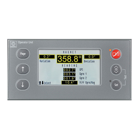
1 Description Fig. 4: Operating Elements and Indicators, Magnetic Compass Selected Pos. No. Area / Element Function Information field Varia- Shows the variation in relation to the location tion Information field Devia- Shows the deviation in relation to the ship tion Information field Diff Compares the connected sensors and displays the Gyro/Mag... -
Page 24: Operating Elements And Indicators On Cpu Pcb
1 Description 1.4.1 Operating Elements and Indicators on CPU PCB Fig. 5: CPU PCB, Operating Elements and Indicators Pos. No. Area / Element Description Dip switch B11 Development only Pushbutton B7 Pushbutton Reset to reset the microcontroller Pushbutton B10 Pushbutton Set with illumination LEDs (white) LED H11 LED H14 Pushbutton B9... -
Page 25: Operating Elements And Indicators On Connection Pcb
1 Description Pos. No. Area / Element Description LED H7 LED Alert (red or green) • red, flashing: An alert is active and must be ac- knowledged • red, constant: An already acknowledged alert is still present • green: currently not used Pushbutton B2 Pushbutton Page with illumination LEDs (white) LED H1... - Page 26 1 Description Pos. No. Area / Element Description Interactive relay = system fail Active relay = operation okay Plug B9 24 V DC supply voltage input Lights up (red) if System Fail is active LED H1 Switch B1 Is used to terminate RS422 Out (or RS485) at plug B5 LED H2 Flashes (green) if there is a data transmission via...
- Page 27 1 Description Pos. No. Area / Element Description LED H6 Flashes (green) if there is a data transmission via plug B7 Plug B3 Development only LED H7 Flashes (green) if there is a data transmission via plug B8 Plug B8 CAN2 (of the Dual CAN Bus) LED H22 Lights up (green) if 24.5 V DC for display back- ground illumination is available...
-
Page 28: Functional Description
1 Description Pos. No. Area / Element Description LED H13 Blinks (green) Alive if the Operator Unit is in nor- mal operation Horn H12 Signal horn for acoustical signal 1.5 Functional Description 1.5.1 Dimming The Operator Unit can be centrally dimmed (depending on the configuration, see chapter The Operator Unit can also act as a central dimmer, meaning that other devices follow the dimming value of the Operator Unit. -
Page 29: Can Bus
1 Description Without activating the quick settling within the 3 minutes, the heating stage and settling stage start according to the procedure as described in chapter 2.3.3 and the manuals of Standard 22 and Standard 22 NX, see Tab. Note If several (max. 3) gyro compasses should be activated with the quick settling function, it is recommended to switch on the compasses one after another in order not to exceed the 3 minutes. -
Page 30: Gyro Compass System Remote Control
1 Description 1.5.4 Gyro Compass System Remote Control There is a remote control functionality available for controlling the Anschütz gyro compass system from an external system, such as an INS. The compass system transmits the following data to the INS: • all available headings including source number and talker identifier •... -
Page 31: Main Page: Overview
1 Description 1.6.1 Main Page: Overview This page provides an overview of the connected sensors, see Fig. Depending on the status of the device, heading information is displayed. If several sensors are connected to the Operator Unit, the heading data supplied by the gyro compass designated GYRO is displayed as selected sensor. -
Page 32: Main Page: Heading Monitoring / Service
1 Description 1.6.2 Main Page: Heading Monitoring / Service Heading Monitoring Within the compass system, all connected heading sensors are compared with each other in order to monitor and display the difference of a defined threshold. If the sensor difference is greater than the user threshold value, an alert Heading Difference Gyro/Gyro (GPS) or Heading Difference Gyro (GPS)/Magnetic is displayed and has to be acknowledged, see chapter... -
Page 33: Display Page: Auto Heading
1 Description Service WARNING! Danger due to unskilled personnel Risk of malfunction or material damage • Perform all configuration and changes only by well-trained Anschütz service personnel. Note To enter the service mode, see chapter 2.4.4.1. If nothing is changed and no submenu is selected, the service page switches back to the overview page after approx. -
Page 34: Fig. 11: Display Page: Auto Heading
1 Description Fig. 11: Display Page: Auto Heading Pos. No. Area / Element Description Indication Selection Appears on the display whenever a selection is possible possible Press pushbuttons Select (Fig. 3/1/2) to navigate through the display. Indication Remaining Shows the remaining time until it switches back to Time the overview page Softkey Back... -
Page 35: Display Page: Speed Error Correction
1 Description There is no message in case of a manual switchover. * XXX can be Gyro, GPS THD or Mag. 1.6.2.2 Display Page: Speed Error Correction The heading of gyro compasses is affected by the speed of the vessel and the latitude where the vessel is operating. -
Page 36: Display Page: Dv-Bus
1 Description Disadvantage: Heading monitoring systems or subsequent systems such as DP systems are not able to detect heading errors caused by wrong speed or latitude data. 3. Input via Standard 22, Standard 22 NX or Standard 30 MF gyro compass (Individual Speed Error Correction): Only available if the system components support this function –... -
Page 37: Display Page: Speed Source Du
1 Description Fig. 13: Display Page: DV-Bus To connect the DV bus and to set the address, see chapter 2.4.4.3. 1.6.2.4 Display Page: Speed Source DU The source of the speed and the type of speed – necessary for the speed error correction –... -
Page 38: Display Page: Heading Uncorrected
1 Description Display Description Course over ground and ground speed VBW Wtr Water speed VBW Gnd Ground speed selected Connected and selected available Connected but not selected not available Possible but currently not connected For changing the speed source, see chapter 2.4.2.2. -
Page 39: Display Page: Deviation Table
1 Description Note RoT data are displayed unfiltered; selected damp values only act to an analogue output (for example: the output RoT in the Distribution Unit, type 138-118). Fig. 16: Display Page: Rate of Turn Display Description + / green bar Rate of turn to starboard - / red bar Rate of turn to port side... -
Page 40: Display Page: Gyro Data
1 Description Note Variation and deviation are used to determine the true magnetic heading and must be checked and updated by the user. Fig. 17: Display Page: Deviation Table Display Description of the Options Edit value and set val- A correction value can be edited and/or set Erase value Erases a selected value Erase all values... -
Page 41: Fig. 18: Display Page: Gyro Data
1 Description Fig. 18: Display Page: Gyro Data Display Function Gyro1/14 Displays the designation of the gyro and the CAN bus address: Gyro 1 / CAN bus address 14 Temperature Temperature of the supporting liquid Gyro supply Supply voltage of the gyro sphere Gyro current Current consumption of the gyro sphere Pump supply... -
Page 42: Display Page: Can-Devices
1 Description 1.6.2.9 Display Page: CAN-Devices The CAN devices submenu displays the Unit ID and the CAN bus status of all devices connected to the CAN bus. Note External devices, which are connected via a serial connection (Distribution Units) are not displayed because in this case the DU is the CAN bus device. -
Page 43: Display Page: Software Versions
1 Description 1.6.2.10 Display Page: Software Versions The software versions of the connected Anschütz devices (gyro, Distribution Unit) are displayed in this submenu. Note The software versions for the MINS and non-Anschütz devices are not displayed. Fig. 20: Display Page: Software Versions (Figure may vary from actual device) Pos. -
Page 44: Main Page: Rot / Roll / Pitch
1 Description Fig. 21: Main Page: Heading Pos. No. Designation Function Heading Shows the heading of the selected sensor Tendency Bar Displays the rate of turn value in the tendency bar A positive sign and a green bar stand for a rate of turn to starboard. -
Page 45: Main Page: Alerts
1 Description Fig. 22: Main Page: RoT / Roll / Pitch Pos. No. Designation Function RoT tendency bar Displays the rate of turn value in the tendency bar RoT value Displays the rate of turn value Roll tendency bar Displays the roll value in the tendency bar Roll value Displays the roll value Pitch tendency bar... -
Page 46: Bridge Alert Management
1 Description Fig. 23: Main Page: Alerts, Unacknowledged Pos. No. Designation Function State Shows the priority of the alerts. For detailed information, see chapter 3.2.2. Alert Text Shows the device and the Unit ID and the alert message, see chapter 3.2.2. For detailed information of the alert messages, see chapter 3.2.2. -
Page 47: Tab. 7: Alert List, Alarm Symbols
1 Description On the bridge alerts are presented on the individual equipment and / or on a . Alerts are divided in different priorities: • Emergency alarm Highest priority of an alert. These alarms show immediate danger to human life or to the ship and its machinery and demand immediate action. -
Page 48: Tab. 8: Alert List, Warning Symbols
1 Description Symbol Description Rectified – unacknowledged alarm (flashing) Active – responsibility transferred alarm Tab. 8: Alert List, Warning Symbols Symbol Description Active – unacknowledged warning (flashing) Active – silenced warning (flashing) Active – acknowledged warning Rectified – unacknowledged warning (flashing) Active –... -
Page 49: Tab. 11: Acknowledge Not Allowed Symbols
1 Description Tab. 11: Acknowledge Not Allowed Symbols Icon/Sym- Description Emergency alarm – acknowledge not allowed Alarm – acknowledge not allowed Warning – acknowledge not allowed Edition: 001 10000001976... -
Page 50: Operation
2 Operation 2 Operation 2.1 Preliminary Remarks User Rights The manual is a complete documentation of the system or equipment. Some functions may not be accessible depending on user rights. All functions or operations are described irrespective of the actual user rights of the user. Markup Elements The manual uses different markup elements for hardware and software. -
Page 51: Setting Into Operation
2 Operation CAUTION! Danger due to improper operation Risk of material damage or malfunction • Reset alle Distribution Units and Operator Units after changes in the configuration of the Individual SEC and DV Bus service page. • Perform changes to all Distribution Units and Operator Units in a compass system. -
Page 52: Fig. 24: Display Page: Heating Stage
2 Operation Heating Stage During the heating stage of the gyro system the heading information is not valid, which is indicated by a set of dashes (- - - .-°). The heating stage is displayed below the heading information, see Fig. If a second gyro is connected, the heating stage is indicated with (Heating) next to heading information of the unselected gyro. -
Page 53: Activate Quick Settling
2 Operation 2.3.4 Activate Quick Settling Procedure If quick settling is possible for a selected gyro compass, this is shown on the display, see Fig. Fig. 26: Display Page: Quick Settling possible 1. Press pushbutton Page. 2. Select Yes to confirm the quick settling process. ►... -
Page 54: Normal Operation Procedures
2 Operation 2.4 Normal Operation Procedures 2.4.1 General Settings 2.4.1.1 Select a Menu Procedure 1. Press pushbutton Page to navigate through the main pages. 2.4.1.2 Change Values Requirements is shown at the bottom left corner of the display Procedure 1. Press pushbuttons ↑↓ to navigate through the display or to change values. Note If no button is pressed for a period of approx. -
Page 55: Adjust Brightness
2 Operation 2.4.1.4 Adjust Brightness Procedure 1. Press pushbutton ☼ . ► The brightness increases as long as the pushbutton is pressed. 2. Press pushbutton ☼ again to decrease. Note The first operation of the pushbutton always increases the brightness. 2.4.1.5 Color Modes The following color modes for day and night are available: Mode... -
Page 56: Select Display Synchronization And Color Mode For Day And Night
2 Operation Pos. No. Area / Element Function No: The display mode can only be changed at this device. Changes of connected devices do not af- fect this device. Information field Dis- Shows the current previewed color mode play Mode Information field Day Shows the current activated day mode (for switch over between day mode and night mode) Information field Night... -
Page 57: Perform Lamp Test
2 Operation 2.4.1.6 Perform Lamp Test Procedure The lamp test is designed to ensure the proper function of operating and display elements at the device. A lamp test during an alert is not possible. Alerts are not displayed during a lamp test. Fig. -
Page 58: Change Speed
2 Operation Note Not all heading receivers (such as radars) are allowed to use magnetic heading. 2.4.2.2 Change Speed Requirements It is recommended to read the information about Individual SEC first, before the function Individual Speed is applied, see chapter 1.6.2.2. Procedure 1. -
Page 59: Change Variation
2 Operation ► The changed value is displayed in italic characters. 7. Press pushbutton Set to confirm the value. Note Please consider the N / S sign for northern / southern hemisphere when adjusting the latitude. Note Big differences of the latitude value, which may occur while switching over from automatic to manual input, are included into the speed error correction (SEC) calculation for 2-3 hours. -
Page 60: Set Threshold For Heading Monitoring
2 Operation Fig. 30: Display Page: Heading Difference Pos. No. Area / Element Description Diff-G/M Shows and enables the setting of the user thresh- old value for the difference between gyro and magnetic Diff-G/G Shows and enables the setting of the user thresh- old value for the difference between gyro and gyro The following table shows the possible settings for a heading difference. -
Page 61: Service Page Settings
2 Operation 2.4.4 Service Page Settings 2.4.4.1 Open Service Mode Procedure Note If nothing is changed and no submenu is selected, the service page switches back to the overview page after approx. 10 seconds. Fig. 31: Display Page: Service Mode 1. Press pushbutton Page and navigate to the heading difference / service page. 2. -
Page 62: Set Switchover Auto Heading
2 Operation Fig. 32: Display Page: Service Mode, Submenus 2.4.4.2 Set Switchover Auto Heading Procedure Note In case of a failure of the selected heading sensor, an automatic switchover to the next heading sensor can be selected. Gyro, GPS THD or magnetic compass can be selected. GPS THD cannot be selected separately –... -
Page 63: Dv Bus Settings
2 Operation Pos. No. Designation Function to Gyro Shows if an automatic switchover to the gyro com- pass/GPS THD compass is selected to TMC Shows if an automatic switchover to the magnetic compass is selected 1. Open submenu Auto Heading from the service page. ►... -
Page 64: Connect Dv Bus
2 Operation Pos. No. Designation Function Back Switches back to the previous page Set Values Confirms the settings for DV-Bus DV-Bus Shows if a DV-Bus connection to the Distribution Unit is selected Address Assigns an address to the DV bus 2.4.4.3.1 Connect DV Bus Procedure Note... -
Page 65: Change Speed Source Du
2 Operation Note Assign a DV bus address if a DV bus is connected to the Distribution Unit. The address of the Distribution Unit must only be assigned once in the DV bus system. An address between 1 and 15 is possible. 1. -
Page 66: Edit Deviation Table
2 Operation Display Description Puls-Log Puls-Log is selected by default Water speed and heading Course over ground and ground speed VBW Wtr Water speed VBW Gnd Ground speed selected Connected and selected available Connected but not selected not available Possible but currently not connected 1. -
Page 67: Select Damping Of Rate Of Turn
2 Operation 3. Turn the changeover switch to activate the second Distribution Unit. 4. Repeat the whole procedure to edit the deviation table for the second magnetic compass as described in chapter 2.4.4.5. 2.4.4.7 Select Damping of Rate of Turn Procedure Note This operation is only possible if the Distribution Unit 138-118, Standard 22 NX or Standard 30 MF is connected. -
Page 68: Emergency Operation Procedures
2 Operation ► No = The Individual values are not available for speed error correction; only the manual or the auto value is available. Note The option Individual is only available on devices (gyro compass and the Distribution Unit), see chapter 1.6.2.2. -
Page 69: Troubleshooting
3 Troubleshooting 3 Troubleshooting 3.1 Safety Information on Troubleshooting Note After re-connection of interfaces, it takes up to 30 seconds until the correct values are displayed again. Note It is possible that an unacknowledged warning escalates to an alarm - according to regulations. -
Page 70: Supported Alerts And Their Properties
3 Troubleshooting 3.2.2 Supported Alerts and their Properties Tab. 12: Operator Unit, Alert List Alert Alert Title Alert Description Escala- Priority tion Category 3062 System Fault System Fault Warning rean- nounce (Warning) 14212 Degr. Perf. Degraded Performance Warning None 14003 DU Err. Distribution Unit Error Caution None... - Page 71 3 Troubleshooting Alert Alert Title Alert Description Escala- Priority tion Category 14039 CAN_L1 Err. Dual CAN Line 1 Error Caution None 14043 CAN_L2 Err. Dual CAN Line 2 Error Caution None 14046 OU Err. Operator Unit Error Caution None 14049 No CAN Con. No CAN Connection Caution None 14053...
-
Page 72: Responsibility Transfer
3 Troubleshooting Alert Alert Title Alert Description Escala- Priority tion Category 14173 Serial Fail. Serial I/F Com. Failure Caution None 14176 Restart Restart Caution None 14206 Lat. Req. Latitude Input Request Caution None 14209 Speed Req. Speed Input Request Caution None Additional to the alert title and the alert description within this table there will be a prefix to identify the source. -
Page 73: Temporary Silencing
3 Troubleshooting The Operator Unit will not take over the responsibility of alerts from other external devices. Only compass system specific alerts will be handled. 3.2.4 Temporary Silencing It is possible to temporarily silence alerts for the adjusted period of time. There are 2 ways to initiate the silencing: •... - Page 74 3 Troubleshooting Alert Message Possible Cause Remedy Distribution Unit Error Defect of electronic Switch to other Distribution Unit Check Distribution Unit and ex- change it if necessary Speed Error Missing speed input Check data of external speed Defect of electronic Select other speed source with Operator Unit Position Error Missing position input...
- Page 75 3 Troubleshooting Alert Message Possible Cause Remedy Operator Unit Error Defect of electronic Use other Operator Unit Exchange item Magnetic Variation Er- Missing variation input Check data of external position sensor Defect of electronic Check Distribution Unit Voltage Cut-Off Loose connection Check power supply of gyro, Distribution Unit and AC/DC AC supply out of range...
- Page 76 3 Troubleshooting on the performance clearer to the operator, the gyro now triggers the alert Degraded Performance followed by the cause e. g. Speed Input Missing. 10000001976 Edition: 001...
-
Page 77: Installation
4 Installation 4 Installation The installation of an Operator Unit is performed according to dimensional drawing and connection diagram in the annex, see chapter 10.2. Adjustment of DIP switches must be performed according to the configuration sheets in the annex, see chapter 10.2. -
Page 78: General Remarks About Preparing Cable Connections
4 Installation 4.1.2 General Remarks about Preparing Cable Connections WARNING! Danger due to electrical current Risk of death or serious injury or material damage • Make sure that all cables are disconnected from the power supply. • If necessary, measure the voltage beforehand and / or disconnect the relevant distributor. -
Page 79: Fig. 38: Prepare A Cable Entry
4 Installation Fig. 38: Prepare a Cable Entry 7. Insert the earthing insert, the seal, and the washer into the cable gland, place the counter nut last and tighten the nut hand-tight. 8. Strip the cable cores to a length of approx. 15 mm, twist slightly and clamp on the cable end sleeves. -
Page 80: General Remarks About Preparing Common Ground Connections
4 Installation 4.1.3 General Remarks about Preparing Common Ground Connections In order to comply with the stringent requirements, please follow the instructions given below regarding cable connections. Use the cable types specified. CAUTION! Damage to Equipment and Components It is essential to make sure that any equipment and any additional component (options) have common reference to the ship's common ground. -
Page 81: Can Bus At Plugs B7, B8
4 Installation Fig. 41: Supply Voltage Connection at Plug B9 Plug/Terminal Function B9/1 +24 V DC Power B9/2 B9/3 B9/4 4.1.5 CAN Bus at Plugs B7, B8 Note The termination of the CAN bus depends on its application within a compass system. Edition: 001 10000001976... -
Page 82: Status Output System Failure At Plug B4
4 Installation Fig. 42: CAN Bus Connection at Plugs B7, B8 Plug/Terminal Remarks B7/1, B8/1 CAN termination (jumper between terminal 1 and 2) B7/2, B8/2 CAN low (L) B7/3, B8/3 CAN high (H) B7/4, B8/4 CAN ground (GND) 4.1.6 Status Output System Failure at Plug B4 Fig. -
Page 83: Serial In And Serial Out At Plug B5
4 Installation Plug/Terminal Remarks B4/1 B4/3 B4/2 Note The above shown status displays an error mode. Note Make sure that the compass system is connected to a signal / alert panel. It depends on the vessel / regulations whether status contacts are sufficient or whether serial data communication is required. -
Page 84: Relay Switching Outputs 1 To 4 At Plugs B6, B11
4 Installation Note Observe the termination switches B1 (RS422 Out) and B2 (RS422 IN). Observe the switch position of B14, B17 and B16 for RS485 operation. The serial input and output can be used for 2 applications: • • Remote control of the compass system 4.1.8 ... -
Page 85: Digital Inputs 1 And 2 At Plug B10
4 Installation 4.1.9 Digital Inputs 1 and 2 at Plug B10 Fig. 46: Digital Inputs 1 and 2 at Plug B10 Plug/Terminal Remarks B10/1, B10/3 Digital in + (24 V supply) B10/2, B10/4 Digital in - (Input → 24 V or 0 V) Terminals 1 and 2 for Digital in1, terminals 3 and 4 for Digital in2 Note Not used in this application. -
Page 86: System Configuration
5 System Configuration 5 System Configuration The Configuration Tool AS, type NB42-232, see Tab. 3, is necessary to configure the Operator Unit. The use of this Configuration Tool is allowed for Anschütz service personnel only. Configuration for the features to be changed must be set. For the list of configurable features, see chapter 1.3.2. -
Page 87: Tab. 14: Recommended Can Settings According To Devices
5 System Configuration Tab. 14: Recommended CAN Settings according to Devices Devices Unit ID CAN Group CAN Number Operator units 01 - 09 01 - 09 10 - 13 10 - 13 Sensors 14 - 19 14 - 19 (Gyro compass) Distribution units 20 - 29 20 - 29... -
Page 88: Care And Maintenance
6 Care and Maintenance 6 Care and Maintenance 6.1 Safety Instructions for Installation and Maintenance WARNING! Danger due to maintenance and service by unskilled personnel Risk of serious injury and material damage • Keep all unskilled personnel away from the working area. •... -
Page 89: General Information
6 Care and Maintenance WARNING! Danger due to damaged cable coating Risk of fire or electrical shock • Do not bend cables to an acute angle, pinch, twist, or impact excessive force while connecting cables to the equipment. • Observe cables for cracks and damge to the cable coating. •... -
Page 90: Maintenance
6 Care and Maintenance 6.3 Maintenance The Operator Unit is maintenance-free. 6.3.1 Maintenance Schedule Tab. 15: Maintenance Schedule Maintenance Interval Remarks Perform lamp test, see chapter 2.4.1.6 Every 6 months 6.4 Repair A repair of the Operator Unit is performed as a replacement of the complete device. After replacement, the Operator Unit must be checked for correct functioning. -
Page 91: Transport And Storage
7 Transport and Storage 7 Transport and Storage 7.1 Preservation, Packing and Storage Preservation All components / devices require no special preservation procedures. Packing All components / devices are packed with a special protection against humidity. The package contains desiccants and a humidity indicator. The humidity indicator can be read from the outside through a window and must be checked regularly. -
Page 92: Transport
7 Transport and Storage Color Indication Inside Humidity Necessary Action 40 % patch: pink > 40 % Desiccants must be replaced Components / devices must be checked for hu- midity, 50 % patch: pink > 50 % Desiccants must be replaced, Packaging must be checked for damages Note Opening and closing the packing to exchange the desiccants must be done by... -
Page 93: Disposal
8 Disposal 8 Disposal The Operator Unit or components of it can be disposed according to the respective national regulations for electronic waste without harmful materials (according to Directive 2012/19/EU on waste electrical and electronic equipment (WEEE)). Edition: 001 10000001976... -
Page 94: Spare Parts Catalog
Shows installed quantity of the spare part for this unit or subunit (Quantity Installed) Remarks Shows more information about the spare part 9.3 Operator Unit Fig. No. Designation 1. Part No. Remarks Item No. 2. Part No. Operator Unit 130-626.NG002 E02 4006604 Color: RAL 9005 10000001976 Edition: 001... -
Page 95: Annex
10 Annex 10 Annex 10.1 Definition of Proprietary NMEA Telegrams 10.1.1 NMEA Telegram: PANZHDS Note PANZHDS: all headings and selected source This telegram contains the headings of all sensors within a compass system. The number of the selected source is also part of the content. Fig. -
Page 96: Nmea Telegram: Panzsld
10 Annex 10.1.2 NMEA Telegram: PANZSLD Note PANZSLD: speed and latitude data This telegram contains speed and latitude data used in the compass system for speed error correction. Fig. 48: NMEA Telegram: PANZSLD Remarks • Both fields can be empty (NULL) if the selected speed or latitude is not available (e. g. in case of individual speed error correction). -
Page 97: Drawings
10 Annex • From external system to compass system (new values to be used by the compass system) 10.2 Drawings Edition: 001 10000001976... - Page 98 10 Annex 10000001976 Edition: 001...
- Page 100 r·-·-·-·-·-·-·-·-·-·-·-·-·-·-·-·-·-·-·-·-·-·-·-·-·-·-·-·-·-·-·-·-·-·-·-·-·-·-·-·-·-·-·-·-·-·-·-·-·-·-·-·-·-·-·-·-·-·-·-·-·-·-·-·-·-·-·-·-·-·-·-·-·-·-·-·-·-·-·-·-·-·-·-·-·-·-·-·-·-·-·-·-·-·-·-·-·-·-·-·-·-·-·-·-·-·-·-·-·-·-·-·-·-·-·-·-·-·-·-·-·-·-·-·-·-·-·-·-·-·-·-·-·-·-·-·-·-·-·-·-·-·-·-·-·-·-·-·-·-·-·-·-·-·-·-·-·-·-·- r-·---------------------------------------------------------------------------------------------------------------------------------------------------------------------------------------------------------------------------------------------------------------------------------------·-· NE06-361 DEEUG SIGNAL OPERA TOR UN IT AS PCE RELAY SWITCHING OUTPUT SYSTEM FAILURE RS 422 ,------- ,.., X X Z X X CAN 1 CAN 2 1- 1- l.!l ,:,: ,:,: [ __ _ , _ -- - -- ·-·-· ·-·-· i <...
- Page 101 GENEHMIGT VON conform BAUELEMENTE NACH WN 246 HTEN 03 500000046811 04.09.23 K ONF IGURA T IONS BLATT / 02 500000040960 14.02.17 CONF IGURATION SHEET ANSCHUTZ 01 500000040460 22.06.16 ZEICHNUNGSNUMMER BLATT 130-626.HP010 00 500000039604 09.06.15 VER. !\NDERUNG AUS GABE DATUM NAME...
Need help?
Do you have a question about the 130-626.NG002 and is the answer not in the manual?
Questions and answers